Several components for hifi/home audio in used condition are danger even outside of operation, because the integrated capacitors in the mains inlet C14 plugs are not disconnect from mains after switch off the component (and not to check and for replace).
Therefore the aging is more extend and it is not possible to check the condition like describe under
because the parts are potted and thus not accessible without destroy.
A friend of me observe such IEC C14 inlet versions with internal burning parts in his Linn Pre-amp KAIRN and Linn CD Player KARIK (unfortunately covered in a black shrink) exact according the description under this URL's:
https://www.vintage-radio.net/forum/showthread.php?t=88137
https://www.vintage-radio.net/forum/showthread.php?t=82160
https://www.vintage-radio.net/forum/showthread.php?t=69128
His apartment smelled extremely unpleasant despite ventilation for many days after this event.
Are the problems in this mentioned threads extremely rare ?
Because there is no access for replace the bad X2 capacitor - go to
only the possibility for whole replacing exist of course with the risk of the same issue after a certainly period of use (because all parts are always connected to the mains even after switching off the main switch).
Thank you for comments.
P.S.: In general I strongly recommend always to replace by a passive inlet (i. e. without integrated RFI parts) according the attached images No. 8-10
Additional an external RFI unit resp. mains filter according those under
https://www.audiomisc.co.uk/mains/filters1.html
or according the attached images No 11-16
but connected behind and not before the mains on/off switch.
This threads don't provide the wanted information:
Therefore the aging is more extend and it is not possible to check the condition like describe under
First various URLs with images of the asked X2 capacitors:
https://www.technikundnatur.eu/revox-mehr/die-rifas.html
Mike's TRS-80 Pages
capacitor - Replacement cap (filter / choke) for oscilloscope power supply - Electrical Engineering Stack Exchange
Beware Rifa Class X Capacitors! - UK Vintage Radio Repair and Restoration Discussion Forum
https://www.eevblog.com/forum/chat/old-rifa-capacitors-and-a-disaster-story/
and
https://www.mikrocontroller.net/topic/170923
Why do these versions in particular fail so often (unfortunately often associated with...
- tiefbassuebertr
- Replies: 50
- Forum: Parts
A friend of me observe such IEC C14 inlet versions with internal burning parts in his Linn Pre-amp KAIRN and Linn CD Player KARIK (unfortunately covered in a black shrink) exact according the description under this URL's:
https://www.vintage-radio.net/forum/showthread.php?t=88137
https://www.vintage-radio.net/forum/showthread.php?t=82160
https://www.vintage-radio.net/forum/showthread.php?t=69128
His apartment smelled extremely unpleasant despite ventilation for many days after this event.
Are the problems in this mentioned threads extremely rare ?
Because there is no access for replace the bad X2 capacitor - go to
Thank you for comments.
P.S.: In general I strongly recommend always to replace by a passive inlet (i. e. without integrated RFI parts) according the attached images No. 8-10
Additional an external RFI unit resp. mains filter according those under
https://www.audiomisc.co.uk/mains/filters1.html
or according the attached images No 11-16
but connected behind and not before the mains on/off switch.
This threads don't provide the wanted information:
Hi Guys,
Trying to replace a failing Schaffner inlet filter (Fn-376- single fused,voltage selector) with a brand new Delta (03sb4- double fused,voltage selector) and can use some input on how to correctly wire things to the new filter, as they are slightly different. I will be using it on 240V primarily, but would like to maintain compatibility to the 110-120V if needed.
I've attached some pictures and a drawing of the old and new inlet filter.
Thanks a lot for your input...
- Loekie1
- Replies: 1
- Forum: Digital Source
Hello,
I was looking at some commercial IEC filters with an intention to clone them. My understanding is that even if the schematics are available, the lay out and actuall construction might be critical for performance so this would be a good reason to buy the ready products. But my little research left me with more questions about how to choose them. In particular, among the models for different current consumption, the only thing that change is the inductor's value: as the current goes up inductance goes down. I suppose it has to do with inductor's saturation but anyway how do we choose...
I was looking at some commercial IEC filters with an intention to clone them. My understanding is that even if the schematics are available, the lay out and actuall construction might be critical for performance so this would be a good reason to buy the ready products. But my little research left me with more questions about how to choose them. In particular, among the models for different current consumption, the only thing that change is the inductor's value: as the current goes up inductance goes down. I suppose it has to do with inductor's saturation but anyway how do we choose...
- MagicBus
- Replies: 30
- Forum: Power Supplies
Simple question... I'm going to use a fused mains inlet from Schaffner and I just assumed the version with filter was the smart choice to reduce noise conducted into the amp.
It has since been suggested that it would be unwise to filter the mains.
What say you, learned folk? Filter or no filter?
Pops
It has since been suggested that it would be unwise to filter the mains.
What say you, learned folk? Filter or no filter?
Pops
- popchops
- Replies: 37
- Forum: Power Supplies
Hi folks.
Has anyone used one of the below sockets?
I'd like to try mains filtering but I'm absolutely not spending a small fortune.
IEC mains filter doo dah

Has anyone used one of the below sockets?
I'd like to try mains filtering but I'm absolutely not spending a small fortune.
IEC mains filter doo dah
- Borats Baby
- Replies: 42
- Forum: Parts
I came across this and wondered if it would do anything to increase the sound quality of the pre-amp I'm building.
https://www.arrow.com/en/products/0...UFaQod4zIMvw&gclid=CI6ltPj36coCFQUFaQod4zIMvw
https://www.arrow.com/en/products/0...UFaQod4zIMvw&gclid=CI6ltPj36coCFQUFaQod4zIMvw
- djn
- Replies: 11
- Forum: Power Supplies
Hi guys.
I've got one question.
I've got one IEC filter that I want to use in my power supply.
That PS contain two grounds DGND and AGND.
Both are tied together in one place via 0 ohm resistor (on another, separated board).
So which ground should I pick to connect it to IEC filter.
Should I connect it to power supply board or to board when ground are tied together (dac board etc.).
That connection should be direct or via 10-100ohm resistor (+ 100nF capacitor in parallel)?
Cheers.
- mikolaj612
- Replies: 6
- Forum: Power Supplies
Which way up do/would you mount IEC mains connectors (earth up or earth down), and are you in 50Hz land or 60Hz land?
I think it'll be divided about 50/50, and have a theory why.....
I think it'll be divided about 50/50, and have a theory why.....
IEC power inlets of course come in all price ranges and I plan on getting a few of the Furutech and other "audiophile" ones and AB them against the poly glass non magnetic cheap ones from parts express in the near future with the same amp wires speakers etc and see if anything is audible at all from them. Of course this experiment can be money wasted and time wasted and wondering if anyone has tried this and what the experiences and results were. Surely someone here has tested this before not just by ear but also with testing equipment probably better then I have access to. Anyone care to...
Attachments
-
 Schaffner Filter FN236B blown solder side-I.jpg62.4 KB · Views: 60
 -
 Schaffner burned.jpg51.5 KB · Views: 50
 -
 Schaffner overheating.jpg31.4 KB · Views: 51
 -
 Schaffner Filter FN323B blown botton view.jpg48.2 KB · Views: 50
 -
 Schaffner Filter FN323B blown top view.jpg48.5 KB · Views: 56
 -
 Schaffner Filter FN236B blown top view.jpg51.5 KB · Views: 54
 -
 Schaffner Filter FN236B blown solder side-II.jpg52.1 KB · Views: 57
 -
 IEC C14 inlet without filter parts.webp47.6 KB · Views: 42
 -
 Schurter IEC C14 inlet without filter parts.jpg27.6 KB · Views: 50
 -
 IEC C14 inlet+fuseh. without filter parts.jpg48.8 KB · Views: 45
 -
 IEC C14 inlet external filter parts.webp23 KB · Views: 51
 -
 IEC C14 inlet external filter parts-II.webp24.2 KB · Views: 56
 -
 mains-filter-PCB.jpg9.7 KB · Views: 61
 -
 mains-filter elektor 10-2007.webp137.2 KB · Views: 63
 -
 mains-filter elektor 10-2007-II.webp71.9 KB · Views: 62
 -
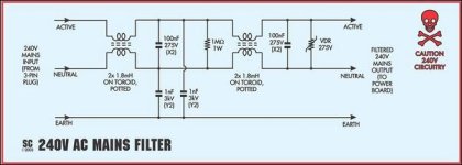
 Multi-RFI low pass and passive IEC C14 inlet.jpg168.6 KB · Views: 71
 -
 RFI (low pass) line filter 24db.gif16.8 KB · Views: 68
 -
 RFI (low pass) line filter.jpg19.6 KB · Views: 66
Last edited:
Or you choose wisely and choose one with a DPST mains switch and fuses integrated. It is always more safe to switch stuff really off (both L and N) and separated from the grid when unattended.
Anyway, the Schaffner filtered IEC inlets with exploding internal RIFA PME series caps are a known issue but these are very old and the RIFA PME caps are very bad. Those RIFA PME also explode in other old devices. Their plastic casing cracks and then moist/dirt can creep in which is not beneficial for their longevity. Many parts are subjected to being energized 24/7 which does not necessarily needs to be a problem. X and Y caps in all their variants are designed for that. These RIFA PME decided that they did not want to take part in such activities anymore.
In other words there is no real common problem we need to panic about and there is absolutely no valid reason to advise to replace filtered IEC inlets for unfiltered ones. Unless one has the particular IEC inlets by that brand with that capacitors. It could be a good idea to check old devices coming in (the price one pays for gathering/hoarding old stuff) for that particular brand and replace the decades old filtered IEC inlets without hesitation for recent ones. Also to be cautious when seeing any RIFA PME in whatever device and replace those also rücksichtslos for a recent cap with similar or better properties. Solved.
Last edited:

Regarding my diy filter linked above, all info I can provide is that it does have a DPST switch and a bleeder resistor first thing after mains and the capacitors used are Pilkor X2 and JEC Y2 -because these were available at the time. Quite a few years in use and no problems so far.
Don't quote me on that but I think that safety regulations (like CE) allow dual fuse inlets only on medical equipment. AFAIK the reason is that if the neutral fuse go poof, you still have mains going into the unit without realising it (or something along these lines anyway... 🙂
Point being that one can not distinguish neutral from phase if you don't know how the plug is plugged in and/or how L and N are wired in the wall socket. Schuko wall sockets are not polarized so what today is L may be N tomorrow and L again next week. Therefor recent IEC inlets have 2 identical fuses.
The meanwhile standard DPST mains switch will take care for complete separation from the grid just like pulling the plug out when there is a defect (standard procedure).
The meanwhile standard DPST mains switch will take care for complete separation from the grid just like pulling the plug out when there is a defect (standard procedure).
Last edited:
read about this problem (blown x2 capacitors) before and on one radio builder site there is the recommendation to put a fuse in line with this cap.
Is this a protection if it fails one day?
Is this a protection if it fails one day?
No normally we replace unreliable stuff for reliable stuff and we clearly define which brand(s) and series were/are affected.
Stating that all filters are problematic is like stating all germans have no humor.
A fuse in series with a cap is a bad idea as when it blows one will have no filtering (without knowing).
Stating that all filters are problematic is like stating all germans have no humor.
A fuse in series with a cap is a bad idea as when it blows one will have no filtering (without knowing).
Last edited:
Point being that one can not distinguish neutral from phase if you don't know how the plug is plugged in and/or how L and N are wired in the wall socket. Schuko wall sockets are not polarized so what today is L may be N tomorrow and L again next week. Therefor recent IEC inlets have 2 identical fuses.
The meanwhile standard DPST mains switch will take care for complete separation from the grid just like pulling the plug out when there is a defect (standard procedure).
I understand all that and I totally agree but still, I think that EU directives call for a single fuse. I'm not 100% sure though.
If so it is strange that many recent ones with internal filtering have 2 fuses (and thankfully also double pole switching) as a standard. I also use ones with 2 fuses as one day these turned out to be standard but I will look it up when I have the time. It seems that it has to do with the internal filtering that may pose a threat to safety when things go south.
Last edited:
It also sounds strange to me but as I said I'm not 100% sure. I know by fact that this was the requirement in UK but they're wise enough to have polarized plugs.
Not sure if that is wise as possible human error is now a built in factor. Probably the polarizing makes a single fuse in L mandatory.
Well, at leat there is some "standard" that has to be met. In Europe L/N are all over the place. Anyway, all that it's a bit off-topic 🙂
Please, do let us know if you find any more info regarding the single/ dual fuse requirements.
Please, do let us know if you find any more info regarding the single/ dual fuse requirements.
Yes because it does not matter at all (by design and standard) and plugging in needed to be a one hand operation regardless of position. L, N and PE are done very strict in home installations with wiring, just not with plugable appliances. As Schuko is used in about the whole of Europe things must have some qualities.
A bit like USB-C, no one cares how it is plugged in as long as one does not need to think about it and stuff just works.
A bit like USB-C, no one cares how it is plugged in as long as one does not need to think about it and stuff just works.
Attachments

Last edited:
How is it safe if there's only one fuse and in some countries the fuse is across the Live and in some others across the Neutral?
Because of the basic principle that the fuse protects the wiring and current flows through the circuit containing the load. Too much current or a short circuit in that circuit and the fuse blows. Regardless of where it is in the circuit and regardless if plugs are polarized or not.
It is almost hard because of its simplicity 😉
It is almost hard because of its simplicity 😉
Last edited:
Sorry to insist (maybe because of luck of knowledge) but if the fuse is across the N and it blows, there's still danger for electrocution under some conditions, right?
Maybe in the UK but the rest of the world uses fuses to protect wiring. PE and residual-current breakers are used to protect against electrocution.
The 2 fuse approach is probably a new phase in “hypersafety” thinking but the basic principle still works OK. Fuses are the KISS principle in optimal form.
Let’s assume the fuse is in the N and it blows because of a defect in the device. Protocol is to switch the device off as it is defective and also to plug it out. Only a fool starts fiddling in defective devices still plugged in.
Things start to get nasty when only N or L are switched in normal off situation and devices seem deenergized but aren’t. That is not a defective device but a defective method.
Last edited:
a circuit breaker on the Neutral has to be linked to the circuit breaker on the Hot (so if one trips, they both trip).
a fuse on the Neutral is a bad idea.
a fuse on the Neutral is a bad idea.
This is also my understanding and I believe the reason that it's not recommended on safety regulations (again, I might be wrong about the regulations)
Perhaps this deserves its own topic as it's somewhat irrelevant to this topic.
Perhaps this deserves its own topic as it's somewhat irrelevant to this topic.
It is not as recent IEC inlets have both. The fuse only in N was hypothetical. It will still blow when things go wrong as current does not care about where the fuse is (in case of a device fault). Current is quite woke.
Modern circuit breakers indeed switch both L and N but this is another level, in the distribution panel not locally in a device.
Modern circuit breakers indeed switch both L and N but this is another level, in the distribution panel not locally in a device.
Last edited:
- Home
- Amplifiers
- Power Supplies
- Blown X2 Cap in Mains Inlet RFI Power Filters (IEC C14, Schaffner, Schurter and others)