Hello,
This thread is created to discuss the BC-1 amplifier design and implementation as described in chapter 4 of Bob’s 2nd edition of the “Designing Audio Power Amplifiers” book.
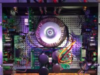
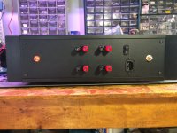
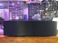
We decided to put BC-1 in a hifi2000 Dissipante 3Ux300mm chassis as a means to have a complete design and as I put it, a reference design right down to the finest of details to make the build as easy as possible. It was done this way since it involves mechanical work such as heatsink drill and tapping that could be done by the chassis mfg as an additional cost if required.
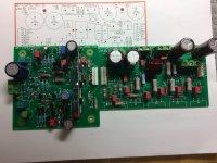
The pcbs were designed to fit on the heatsinks and that chassis with a base pan.
The pcb set has mirror images pcbs for those heatsinks mounted on left and right sides.
As a beta tester I was hoping that you would review my build guides and assembly procedures for that chassis build.
Not to say that the design can’t be put in a different chassis but it was optimized and laid out for that particular chassis. Which means you will probably be on your own for mechanicals in a different chassis.
Still interested?
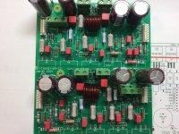
When I get on the computer I can show a few pics of the completed design
This thread is created to discuss the BC-1 amplifier design and implementation as described in chapter 4 of Bob’s 2nd edition of the “Designing Audio Power Amplifiers” book.
We decided to put BC-1 in a hifi2000 Dissipante 3Ux300mm chassis as a means to have a complete design and as I put it, a reference design right down to the finest of details to make the build as easy as possible. It was done this way since it involves mechanical work such as heatsink drill and tapping that could be done by the chassis mfg as an additional cost if required.
The pcbs were designed to fit on the heatsinks and that chassis with a base pan.
The pcb set has mirror images pcbs for those heatsinks mounted on left and right sides.
As a beta tester I was hoping that you would review my build guides and assembly procedures for that chassis build.
Not to say that the design can’t be put in a different chassis but it was optimized and laid out for that particular chassis. Which means you will probably be on your own for mechanicals in a different chassis.
Still interested?
When I get on the computer I can show a few pics of the completed design
Attachments
-
 IMG_0844.JPG560.7 KB · Views: 1,436
 -
 IMG_0845.JPG457.4 KB · Views: 1,287
 -
 IMG_0846.JPG407 KB · Views: 1,431
 -
 BC-1 Assembled pcbs-2.JPG415.6 KB · Views: 1,336
 -
 BC-1 Assembled pcbs-6.JPG483.1 KB · Views: 1,250
 -
BC1 Schematic - Rick.asc21.9 KB · Views: 308
-
BC1 Schematic - Rick.pdf45.4 KB · Views: 557
Last edited by a moderator:
It depends on the transformer, we had this conversation, went like this, but it was determined that 100VCT is needed, since 90VCT is a little shy of the target 150W/8 ohm.
So its 500-650VA for that chassis as it is laid out in the pic. I used a Triad VPT100-5000, since it was a good deal at Arrow, shipping was free, Mouser wanted more plus extras for shipping, same for Parts-Express.
So its 500-650VA for that chassis as it is laid out in the pic. I used a Triad VPT100-5000, since it was a good deal at Arrow, shipping was free, Mouser wanted more plus extras for shipping, same for Parts-Express.
Based on what I know so far, I'll probably be recommending a 50-0-50 V or 45-0-45 V transformer with a VA of at least 500 VA. Obviously, these are soft criteria, since choice of power and current capability is somewhat optional. I think we would like to see at least 150 wpc, both channels driven into 8 ohms. How that translates to 4-ohm power is somewhat optional, and where VA comes in to play a bigger role, since it affects the stiffness of the power supply. An amplifier with a very high VA transformer might approach double power at 4 ohms, for example

First of all, Rick deserves great credit for making this design a buildable reality. His PCBs are superb and professional, and his physical design expertise is very valuable. Those of you familiar with the DH-220C know of Rick's expertise. Rick has actually built the completely-assembled unit first, while I put the two amplifier modules through their paces.Let us hear from Bob Cordell on his BC-1.
My recent testing of the module has been with the DH-220C power suppy, whichs puts out about 64V rails at no load.
At 1 kHz into 8 ohms, it clips at 171 watts, one channel driven.
At 1 kHz into 4 ohms, it clips at 306 watts, one channel driven.
At 1 kHz into 2 ohms, it clips at 364 watts, one channel driven.
Significantly, the amplifier is a good performer into a 2-ohm load. At 1 kHz and 312 watts into 2 ohms, THD was only 0.0025%.
At 160 watts into 8 ohms, THD at 20 kHz was 0.0025%.
The frequency response is down 3 dB at 650 kHz with no peaking. The 10 kHz squarewave looks quite good, with no overshoot or ringing.
Intended in the book as a straightforward starter amplifier project, the amplifier design is not fancy or complex. It uses standard Miller compensation and a 3 EF Locanthi T-circuit output stage.
Cheers,
Bob
Sorry for the late reply. Yes, the BC-1 uses 2 output pairs. I do not see a problem with taxing the drivers when driving reasonable loads. I have driven the BC-1 to clipping into 2 ohms for brief intervals, and there has been no problem. Of course, I certainly would not recommend running at 1/3 power into 2 ohms for an hour. BTW, for a given load, adding another pair of output transistors does not necessarily make the job of the drivers more difficult, since the net current gain of the output stage will be about the same (actually, under some conditions the net current gain of the output stage would be higher due to less beta droop under high-current conditions. Adding another output pair biased the same as the first two would increase idle bias by 50%, and tend to reduce distortion a bit.
Cheers,
Bob
Cheers,
Bob
On the weekend as requested by Bob I performed some protection ckt and thermal testing of Bc-1 with the lm35 attached to the top of the ops bjt closest to the front. With a 4ohm load on that one test channel and running the 1/3 max power test it did not take very long to hit the 70c limit and open the speaker relay. It took a lot longer doing the 8 ohm test. Today I will run the 1/3 max power test for both channels into 8 ohms it might be able to sustain that test indefinitely with the reduced supply V
Clipping levels:
Left Channel Only:
~42Vrms/8-ohm/1kHz= 220W
~37.6Vrms/4-ohm/1kHz= 350W, thd ~-98dB which is at the Amber 3501 residual.
Both channels:
~38Vrms/8-ohm/1kHz = 180W (supply +/-61V)
~21Vrms/4-ohm took about ~5 min to get the relay to trip, TP3@71C,, HS hot spot (measured on the outside bottom front) was ~80C, opposite HS end was ~70C, the front panel gets hot too, as it transfers a lot of heat.
Speaker relay re-energized when TP3 drops to ~60C
24Vrms/8-ohm took about ~25 min for the relay to trip,
Last edited:
Thanks. Much as I suspected. I understand how the net drive current with 3 output pairs could be less. I intend to use the BC-1 on 4 Ohm speakers.Sorry for the late reply. Yes, the BC-1 uses 2 output pairs. I do not see a problem with taxing the drivers when driving reasonable loads. I have driven the BC-1 to clipping into 2 ohms for brief intervals, and there has been no problem. Of course, I certainly would not recommend running at 1/3 power into 2 ohms for an hour. BTW, for a given load, adding another pair of output transistors does not necessarily make the job of the drivers more difficult, since the net current gain of the output stage will be about the same (actually, under some conditions the net current gain of the output stage would be higher due to less beta droop under high-current conditions. Adding another output pair biased the same as the first two would increase idle bias by 50%, and tend to reduce distortion a bit.
Cheers,
Bob
I ran the test: Both channels driven into 8-ohm with a 1kHz sine to determine the FTC rating.
With my BC-1 implementation it would be rated for a min. 150W per channel continuous. The test ran for the hour with the top off.
Nice and hot, I have never done this test before, for one, I did not have the loads, until recently. I was imagining that a speaker would be in melt down in short order at these sustained levels.
THD was at the Amber 3501 residual ~ -100dB, when I measured with some more signal.
The rectifiers on the PS were just a touch warm. the 0.2 ohm CRC was hotter ~60C. I did not, but should have, measured the transformer temp rise. Probably required for a UL/CSA cert.
The amp is a solid performer. The limitation I see to delivering the designs max continuous power is the 3Ux300mm chassis
So to state a FTC rating with both channels: ~38Vrms/8-ohm/1kHz = 180W (supply +/-61V), one must
Use a 4U/300mm or longer 3U/400mm HS/chassis to get you more power dissipation capability, at the sustained levels and maintain the 70C HS temp limit
So it really depends how much power that you actually need? Are the extra costs justified for your situation.
The bottom line is that the design meets the goals set forth IMO.
Great info. Are there any updates to report? A PCB turn or are we still waiting on BC's OK?I ran the test: Both channels driven into 8-ohm with a 1kHz sine to determine the FTC rating.
With my BC-1 implementation it would be rated for a min. 150W per channel continuous. The test ran for the hour with the top off.
Nice and hot, I have never done this test before, for one, I did not have the loads, until recently. I was imagining that a speaker would be in melt down in short order at these sustained levels.
THD was at the Amber 3501 residual ~ -100dB, when I measured with some more signal.
The rectifiers on the PS were just a touch warm. the 0.2 ohm CRC was hotter ~60C. I did not, but should have, measured the transformer temp rise. Probably required for a UL/CSA cert.
The amp is a solid performer. The limitation I see to delivering the designs max continuous power is the 3Ux300mm chassis
So to state a FTC rating with both channels: ~38Vrms/8-ohm/1kHz = 180W (supply +/-61V), one must
Use a 4U/300mm or longer 3U/400mm HS/chassis to get you more power dissipation capability, at the sustained levels and maintain the 70C HS temp limit
So it really depends how much power that you actually need? Are the extra costs justified for your situation.
The bottom line is that the design meets the goals set forth IMO.
Hi,
My reference built has been running for months now. Getting close to an official beta release IMO.
Bob is presently characterizing the optional OPS double-cross feature.
I have just finished the first pass on a 70 page BC-1 document, for Bob to review")
It is a major edit of chapter 4 in the book, detailing design, build, test, specific to the refence build
Stay tuned
My reference built has been running for months now. Getting close to an official beta release IMO.
Bob is presently characterizing the optional OPS double-cross feature.
I have just finished the first pass on a 70 page BC-1 document, for Bob to review
It is a major edit of chapter 4 in the book, detailing design, build, test, specific to the refence build
Stay tuned
Thanks for the update.Hi,
My reference built has been running for months now. Getting close to an official beta release IMO.
Bob is presently characterizing the optional OPS double-cross feature.
I have just finished the first pass on a 70 page BC-1 document, for Bob to review
It is a major edit of chapter 4 in the book, detailing design, build, test, specific to the refence build
Stay tuned
Hi Rick, these are good numbers. Was the amp run at 1/3 power for this test? I believe the FTC test was changed to 1/8 power for an hour. Because different builders may use different power supply transformers, we might also want to specify what the rail voltage is during these tests.I ran the test: Both channels driven into 8-ohm with a 1kHz sine to determine the FTC rating.
With my BC-1 implementation it would be rated for a min. 150W per channel continuous. The test ran for the hour with the top off.
Nice and hot, I have never done this test before, for one, I did not have the loads, until recently. I was imagining that a speaker would be in melt down in short order at these sustained levels.
THD was at the Amber 3501 residual ~ -100dB, when I measured with some more signal.
The rectifiers on the PS were just a touch warm. the 0.2 ohm CRC was hotter ~60C. I did not, but should have, measured the transformer temp rise. Probably required for a UL/CSA cert.
The amp is a solid performer. The limitation I see to delivering the designs max continuous power is the 3Ux300mm chassis
So to state a FTC rating with both channels: ~38Vrms/8-ohm/1kHz = 180W (supply +/-61V), one must
Use a 4U/300mm or longer 3U/400mm HS/chassis to get you more power dissipation capability, at the sustained levels and maintain the 70C HS temp limit
So it really depends how much power that you actually need? Are the extra costs justified for your situation.
The bottom line is that the design meets the goals set forth IMO.
Since good music has significant dynamic range, it will often be brief peaks that need the most power, and this is under a condition that is not thermally constrained. For this reason I also like to quote the short-term power after 15 seconds.
Hello members,
We have completed the 73 page document for BC-1. Design, Build, Testing of two prototypes, Documentation, everything is complete enough to say we are happy and ready for a beta release. The document is a big update for chapter 4 in the 2nd edition of the power amp design book, detailing the building of this reference design I call it.
There are 8 pcbs in total, 7 different types in the design, 2xAFE,2xOPS,2xProtect,1xPS,1xAC
Building BC-1 is far from low cost. I have calculated parts costing in the $800 range, the chassis, transformer, PS make up a good half of that.
It's a lot of $ but worth it as it is a mini battle tank imo.
Let's be serious here, it is not a beginners project by any means. You should have a few builds under your belt to take on this big project.
You will be required to order and machine the Dissipante 3Ux300mm chassis HS's and back panel unless you want to pay for it to be done by HiFi2000, just more costs. You have to order parts from the Mouser shopping carts, solder pcbs, wire, test. There is a cloud link for pics and documents as well.
We are looking for a beta tester, if anyone is interested. I will supply a set of pcb's for the beta tester, in appreciation, for taking on this big task. Getting all the parts is a challenge these days but I see improvement in deliveries. Everyday it changes.
As a beta tester, you will be going over all the documents, reviewing, ordering parts, perform the build and finally testing it out. Of course myself and Bob are your mentors for a beta build. It should be a fun project. We've been at it for a while now so its no rush, a really nice fall/winter project, if all goes well, you might have it under the tree for xmas.
To answer the previous question "Also, when was the start of project BC-1?"
Bob's been at the BC-1 design while preparing and writing the 2nd edition of the book, I've been at it since I've had the 2nd edition book, so its been a while.
Rick
Last edited:
- Home
- Amplifiers
- Solid State
- Bob Cordell’s BC-1 audio power amp