A friend of me get in used condition this satellite speakers (8 pieces model 32) so as two sub-woofers from BOSE's Freespace 3 series II.
Owner's manual is here:
https://assets.bose.com/content/dam...udspeakers/FreeSpaceModel_32/og_fsmodel32.pdf
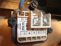
Page 8-9 explains the fittings/setting taps (configuration), but I don't understand, how get I 4Ω or 8Ω. What is to do on the terminal of the 100 V PA-(ELA-) transformer resp. transmitter (go also to image No 5) ?
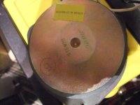
Measuring the DC resistance of the chassis driver led to the result of only 800 mΩ (exact same value of the drivers used in BOSE's 901 series).
Thank you very much for an advice.
Owner's manual is here:
https://assets.bose.com/content/dam...udspeakers/FreeSpaceModel_32/og_fsmodel32.pdf
Page 8-9 explains the fittings/setting taps (configuration), but I don't understand, how get I 4Ω or 8Ω. What is to do on the terminal of the 100 V PA-(ELA-) transformer resp. transmitter (go also to image No 5) ?
Measuring the DC resistance of the chassis driver led to the result of only 800 mΩ (exact same value of the drivers used in BOSE's 901 series).
Thank you very much for an advice.
Attachments
-
 Bose Model 32 Driver 0,8 ohms.jpg988.3 KB · Views: 448
 -
 Bose Model 32 Driver 0,8 ohms-II.jpg985.4 KB · Views: 310
 -
 Bose Model 32 Driver 0,8 ohms-III.jpg1 MB · Views: 295
 -
 Bose Model 32 Driver 0,8 ohms-IV.jpg988.4 KB · Views: 334
 -
 Bose Model 32 100V transmitter jumper terminal.jpg983 KB · Views: 345
 -
 Bose Model 32 100V transmitter jumper terminal-II.jpg746.7 KB · Views: 262
 -
 Bose Model 32 100V transmitter rear.jpg925.2 KB · Views: 253
 -
 Bose Model 32 front open.jpg225.5 KB · Views: 231
 -
 Bose Model 32 front-cover.jpg977.1 KB · Views: 234
 -
 Bose Model 32 front-II.jpg134.4 KB · Views: 241
Last edited:
more images.
There are also stickers, where are 70.7VRMS and 4 Ohms to read.
There are also stickers, where are 70.7VRMS and 4 Ohms to read.
Attachments
-
 Bose Model 32 100V RMS.jpg880.3 KB · Views: 366
 -
 Bose Model 32 inside.jpg1,013.9 KB · Views: 218
 -
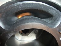 Bose Model 32 vented port.jpg1,004.4 KB · Views: 172
 -
 Bose Model 32 package.jpg293.4 KB · Views: 172
 -
 Bose Model 32 - 4 ohms.jpg109.8 KB · Views: 203
 -
 Bose Model 32 envelope.jpg106 KB · Views: 178
 -
 Bose Model 32 70.7V-RMS.jpg90.6 KB · Views: 163
 -
 Bose Model 32 rear.jpg228.3 KB · Views: 158
 -
 Bose Model 32 mounting kit.jpg473.9 KB · Views: 301
 -
 Bose Model 32 front.jpg675 KB · Views: 181
I would expect you need to measure AC. If you measure the Voltage transformation, you can calculate the impedance.
Markings 1-2-4-8-16-32 are not ohms, but wattage going to the driver, when connected to a 100 V (or 70 V) line amplifier.
0.8 ohm impedance measured is resistance of the primary winding of the 100 V (70 V) line transformer.
Simply remove the 100 V (70 V) transformer from the loudspeaker enclosure and you have a 4-8 ohm driver.
0.8 ohm impedance measured is resistance of the primary winding of the 100 V (70 V) line transformer.
Simply remove the 100 V (70 V) transformer from the loudspeaker enclosure and you have a 4-8 ohm driver.
To confirm actual value, measure and post each speaker DCR on its own, not connected to anything else and of course not any transformer, even if built in.
You want to use them in a way different than originally expected, which is fine.
You want to use them in a way different than originally expected, which is fine.
No. the measured value occurs after remove the transformer.Markings 1-2-4-8-16-32 are not ohms, but wattage going to the driver, when connected to a 100 V (or 70 V) line amplifier.
0.8 ohm impedance measured is resistance of the primary winding of the 100 V (70 V) line transformer.
Simply remove the 100 V (70 V) transformer from the loudspeaker enclosure and you have a 4-8 ohm driver.
It appears with that model, you cannot get a 4-8 Ohm bypass because the driver itself is a 1 Ohm design. In the 901, they were all wired in series. Only way to use them is either with 70/100 volt amplifier or wire all 4 in series with the transformer bypassed.
Greg
Greg
You have mixed models.
The transformerless ones are 4 ohm impedance (so about 3 ohm DCR) and straight usable as such.
The others are either 70V or 100V and that´s what you have, period.
As you measured, those speakers 0.8 ohm DCR so nominal 1 ohm each and yes, same as those in Bose 901 , which uses 8 in series.
There is no way you can set those to 4 or 8 ohm each.
Not sure how many you have, if many you can wire them in strings of 4, to get usable 4 ohm loads.
I find it weird you have such a mixup, in theory Europe uses 100V lines, US version 70V
Oh, I misunderstand you. OK, so you have the infamous 1-ohm BOSE driver in each enclosure. Wire 4 in series and you have an equivalent of a 4-ohm driver.No. the measured value occurs after remove the transformer.
BOSE Model 32 100 VRMS - Auto-Transformer Schematic here
In the attachment the images of transformer with removed connection terminals and partially cut off leads of some winding so as of the steps of the assembly procedure.
First image shows the schematic of the 100V transformer.
According this it is clearly an auto transformer, i. e. no isolation transformer.
It can therefore be assumed that Bose uses this 0.8 ohm chassis in all versions of this model - even in the version with 8 ohms together with a suited auto transformer in this kind but for 8 ohms input.
When such transformers available as a single part for reasonable costs, it would be an easy task to change it in all speaker devices to get 8 ohms and avoid to purchase amp with 100V outputs.
An other possibility is a use of the pins "C" and "32" - this DC-resistance together with the driver is 1R7 and serial connection of two speaker devices is 3R4 - i. e. close enough to typical speakers with impedance of 4 ohms. To be able to say this in advance one would need the circuit diagram (schematic) of the passive high pass in the bass unit from Freespace 3 Series II - go to
Acoustimass Bassmodul Series II | Bose Professional
The installation guide under
http://warehousesound.com/r/boseFREESPACE3manual.pdf
don't mention exact values for the satellite speaker impedance:
You can use the FreeSpace®3 System Series II Acoustimass® module with other Bose® speakers, such
as the FreeSpace Model 16, Model 32, Model 32SE, Panaray® 302TM, or FreeSpace 6 speakers. Just
be sure to connect both the speakers and the module directly to the amplifier, using separate
channels or connect speakers that do not need equalization in parallel with the Acoustimass module
on the same channel.
Attachments
-
 BOSE Autotrafo Model 32 100V schematic.jpg848.4 KB · Views: 2,105
 -
 DSCF7815.jpg984.8 KB · Views: 237
 -
 DSCF7816.jpg857.3 KB · Views: 147
 -
 DSCF7819.jpg982.2 KB · Views: 141
 -
 DSCF7821.jpg817 KB · Views: 190
 -
 DSCF7823.jpg977.5 KB · Views: 126
 -
 DSCF7825.jpg924.5 KB · Views: 150
 -
 DSCF7827.jpg988.3 KB · Views: 159
 -
 DSCF7829.jpg1 MB · Views: 272
 -
 DSCF7831.jpg1,003.9 KB · Views: 197
Last edited:
What is really important is AC impedance between "C" and "32" pins, not DC resistance. With one Bose driver AC impedance between "C" and "32" pins will be 312.5 ohm nominally (with 100V transformer). With two serially connected speakers (with transformers) it will be double - 625 ohm. If you connect them to a conventional amplifier with max output of 100W/4ohm (20 V max), then both drivers can receive max 0.64 W.
All of-the-shelf 100V (or 70V) transformers are made for drivers with nominal impedance of 8 ohm (or 4 ohm). If you connect 1-ohm Bose to such transformer, it can not supply high enough current because it is not designed to do so.
All of-the-shelf 100V (or 70V) transformers are made for drivers with nominal impedance of 8 ohm (or 4 ohm). If you connect 1-ohm Bose to such transformer, it can not supply high enough current because it is not designed to do so.
Obviously you think, this kind of connection (in my schematic) is based on my own idea. But this isn't true.What is really important is AC impedance between "C" and "32" pins, not DC resistance. With one Bose driver AC impedance between "C" and "32" pins will be 312.5 ohm nominally (with 100V transformer). With two serially connected speakers (with transformers) it will be double - 625 ohm. If you connect them to a conventional amplifier with max output of 100W/4ohm (20 V max), then both drivers can receive max 0.64 W.
All of-the-shelf 100V (or 70V) transformers are made for drivers with nominal impedance of 8 ohm (or 4 ohm).
If you connect 1-ohm Bose to such transformer, it can not supply high enough current because it is not designed to do so.
I haven't developed resp. connect this in this kind - this is genuine BOSE construction and design.
My own idea is only using the pins "C" and "32" instead the nominal pins for 100V (for use 4-8 ohms output at usual amp).
Last edited:
I misunderstood you again, my bad.
If the Bose transformer is the auto-type -yes, you can use the "secondary" windings as input.
If the Bose transformer is the auto-type -yes, you can use the "secondary" windings as input.
Close, but not correct. I revisited your schematic (post #10) of Bose 100 V auto-transformer incorporated in Bose 32. You should connect amplifier output to pin "4" and "-", to get 4-ohm nominal impedance. For 8-ohm input impedance connect amplifier to pin "8" and "-".My own idea is only using the pins "C" and "32" instead the nominal pins for 100V (for use 4-8 ohms output at usual amp).
In both instances, connect the driver to pin "1" via pin "C".
1) sorry, but your schematic is wrong on many counts, so much it can´t even be "corrected"
IF I have some free time, I´ll draw the proper one.
In principle you have it the wrong way w.r.t. max/min power sequence, and speaker is not in series with any winding as you show.
2)
Will extend answer later.
IF I have some free time, I´ll draw the proper one.
In principle you have it the wrong way w.r.t. max/min power sequence, and speaker is not in series with any winding as you show.
2)
Transformer DCR and voice coil DCR are completely unrelated and must not be confused with each other.An other possibility is a use of the pins "C" and "32" - this DC-resistance together with the driver is 1R7 and serial connection of two speaker devices is 3R4 - i. e. close enough to typical speakers with impedance of 4 ohms.
Will extend answer later.
1) I don't know whether the schematic @tiefbassuebertr drew in post #10 is correct or not. But if we assume it is largely correct, then the only mistake I see is that the "windings" left and right from the driver (next to "white" and "black" wires) do not exists in reality - they are simply connecting wires. All auto-transformer windings are between Input pins "-" and "+".
When the driver is connected to (one of the) pins "1" to "32" via pin "C", then the driver is parallel to the windings "1" to "32" and the transformer action is possible.
2) You are correct - DCR is not relevant, as I mentioned in post #11, too.
When the driver is connected to (one of the) pins "1" to "32" via pin "C", then the driver is parallel to the windings "1" to "32" and the transformer action is possible.
2) You are correct - DCR is not relevant, as I mentioned in post #11, too.
Last edited:
1) If you are right, it wouldn't be an auto transformer but rather an usual isolation transformer with primary and secondary winding. This isn't definitely the case. But completely unusual but at Bose there are many things that do not conform to the standards (or do you know chassis with 0.8 Ohm DCR?).1) sorry, but your schematic is wrong on many counts, so much it can´t even be "corrected"
IF I have some free time, I´ll draw the proper one.
In principle you have it the wrong way w.r.t. max/min power sequence, and speaker is not in series with any winding as you show.
2)
Transformer DCR and voice coil DCR are completely unrelated and must not be confused with each other.
Will extend answer later.
2) DCR are completely unrelated only in order, what represented the load for the driven power amp stage (except the range below 5-10 Hz). Therefore an impedance-plot resp. impedance magnitude over the frequency is necessary, what I will try to create next time. But DCR is related for creating the schematic for a correct assignment of the individual windings.
Last edited:
Please see my post #14.
1) Your schematic do represent auto-transformer, so my solution in post #14 will work.
2) Driver impedance Z presented to an amplifier (in the range 20 Hz - 20 kHz), via the auto-transformer, is the only impedance you should be worried about. DC resistance of the driver (Re) is already included in the driver impedance Z. Influence of DC resistance of the transformer windings will be small compared to impedance transformed by the auto-transformer (presented to amplifier as load), and can be neglected.
Please measure the impedance-vs-frequency of the system I proposed in post #14.
No, I mean you show, left to right:1) If you are right, it wouldn't be an auto transformer but rather an usual isolation transformer with primary and secondary winding. This isn't definitely the case.
ONE winding at left - a speaker - eight MORE WINDINGS to the right with speaker in series with all windings, and in particular bridging left winding and all those to the right.
That is wrong on many counts.
It IS an autotransformer, but wired this way:

Speaker is always across one or more windings (in parallel), never in series with any of them.
As of : getting 4 -8 ohm impedance instead of almost unusable 1 ohm.
In principle you can use some autotransformer taps for impedance conversion but it has its compromises.
4:1 impedance step-up means 2:1 voltage down or 4:1 power down so you CAN connect speaker between common and 8W tap, then drive 32W tap from an amp which will "see" reflected 4 ohm , so far so good, BUT speaker can only "extract" specified 8W from that tap.
Why?
To be a real impedance converter X-Former, lower voltage (8W) winding should be 1.4X diameter, 2X the area/section than "32W" one to keep power handling constant .
I very much doubt it was wound that way, but constant diameter/area instead.
Why?
1)cost/speed/practicality: it´s easy to stop winder every few turns and take a tap outside; a PITA to change wire diameter and advance pitch every time (I commercially wind transformers) plus these must be cheap and easy, or else. so using same wire on all taps is GOOD.
2) penalty is reduced power handling at lower taps.
Since it´s the PURPOSE of this transformer, everything´s perfect 🙂
Using it as a constant power multi impedance transformer was NOT a requirement.
In a nutshell: you CAN get a usable 4 ohm load from that speaker, penalty is that you can NOT feed 32W to it, because transformer wire will not handle current.
If you have many and can series wire them, perfect.
You gave me the itch to wind a few 70V transformers and install small background music speakers in my 19 room house/workplace.
Although the realistic solution would be to install a Bluetooth or WiFi music server and do it wirelessly.
Thank you very much for your efforts.
The only difference between your and my schematic version are only the two windings in serial to the speaker connection.
If your estimate is right, between "C" and "- in" exist only a connection wire without windings - i. e. without any inductivity.
According the previous images one cannot automatically assume that (post #10, second/fifth image thin wire right side for "-in" and third image thick wire right side for "C").
Checking the impedance plots provides clarity.
After done I will report.
Last edited:
- Home
- Loudspeakers
- Multi-Way
- Bose® FreeSpace® Model 32 - how do I get 4-8 Ohms ?