Hi all.
First post so be gentle.
I'm in the process of renovating some newly aquired B&W DM2, Series 2's and I'm finding getting matching electrical components a real pain in the backside.
Now please consider I'm almost a total newby in the world of audio electronics and have only a basic knowledge at best (we all have to start somewhere eh) so i'll probably end up asking some dumb/obvious questions...bare with me. 😉
Firstly I'm lead to believe that installing a higher voltage capacitor onto a crossover isn't a problem...but how high is it realistic to go? Could iI replace a 25vdc Cap with say a 250vdc cap? This is just a rhetorical question .
The same question regards Capacitance....could i replace say 75uf cap with an 80 or 90uf cap? I understand there will be tonal differences replacing caps with differing Capacitance ratings, so with that in mind i am wanting to keep the sound as close to original spec as possible and to achieve this how much would i be able to adjust the Capacitance rating by? Please stay with me on this.
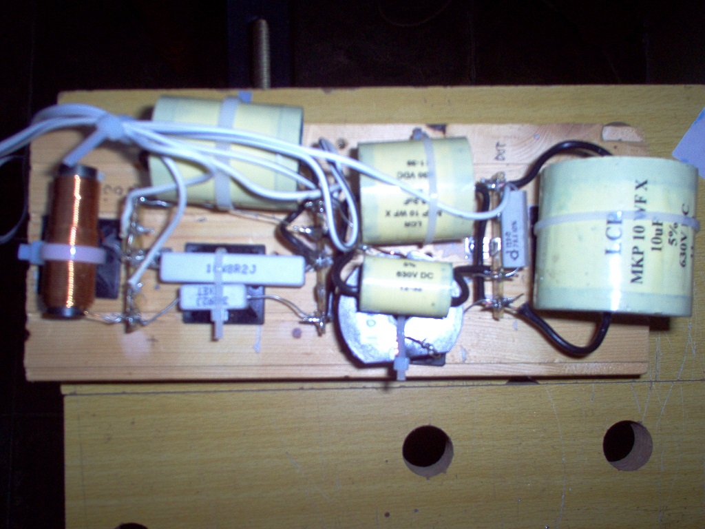
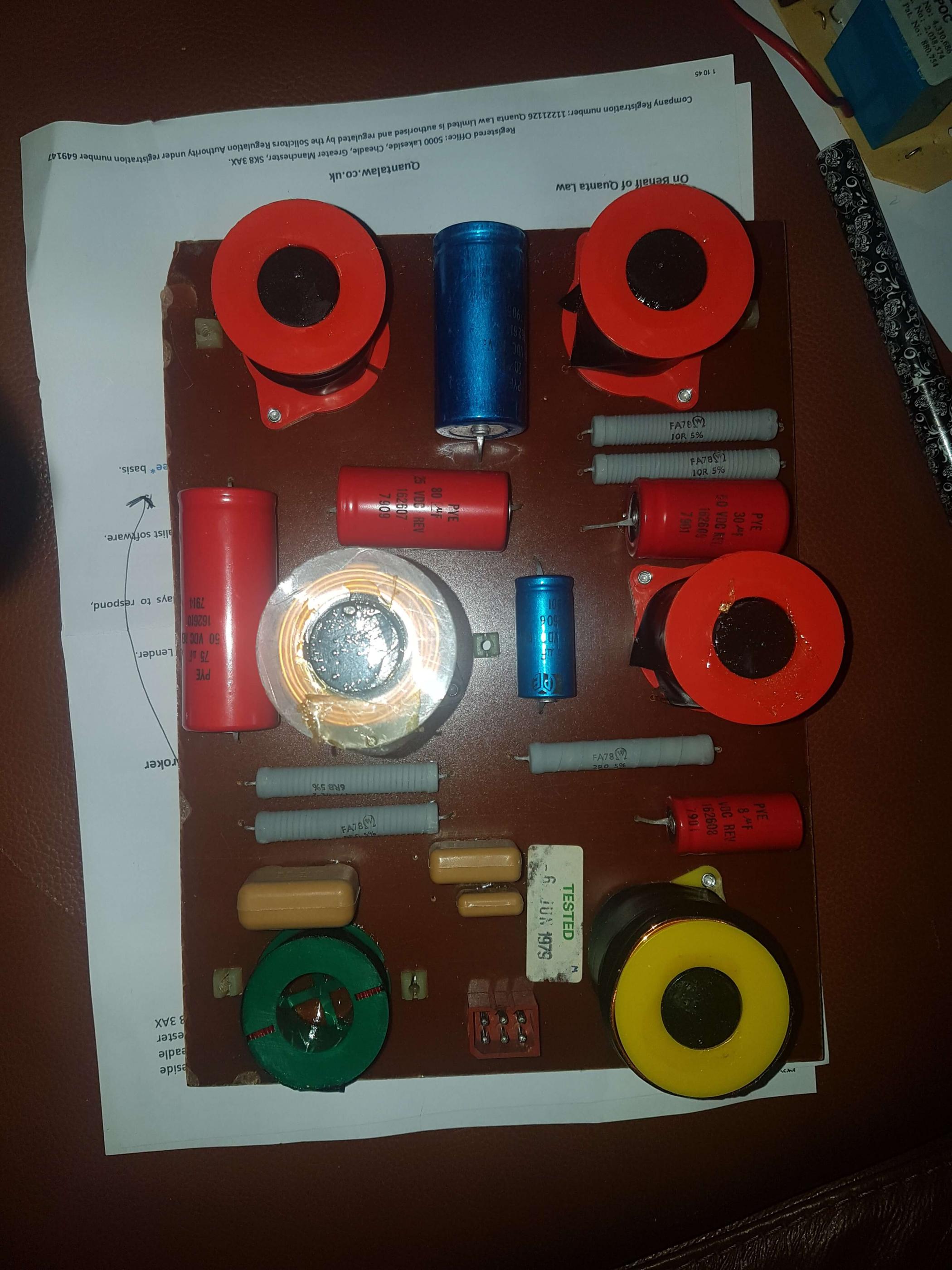
I've put up a couple of pictures and was wondering whether someone could guide me on suitable replacements for the 5 Grey Resistors? The measurements on the side say:
No1(X2) = FA78 Ω (has a "W" in the omega symbol) 10R 5%
No2 = FA78 Ω ( ) 2R0 5%
No3 = FA78 Ω ( ) 6R8 5%
No4 = FA78 Ω ( ) 8R0 5%
Thank you in advance for any guidance.
First post so be gentle.
I'm in the process of renovating some newly aquired B&W DM2, Series 2's and I'm finding getting matching electrical components a real pain in the backside.
Now please consider I'm almost a total newby in the world of audio electronics and have only a basic knowledge at best (we all have to start somewhere eh) so i'll probably end up asking some dumb/obvious questions...bare with me. 😉
Firstly I'm lead to believe that installing a higher voltage capacitor onto a crossover isn't a problem...but how high is it realistic to go? Could iI replace a 25vdc Cap with say a 250vdc cap? This is just a rhetorical question .
The same question regards Capacitance....could i replace say 75uf cap with an 80 or 90uf cap? I understand there will be tonal differences replacing caps with differing Capacitance ratings, so with that in mind i am wanting to keep the sound as close to original spec as possible and to achieve this how much would i be able to adjust the Capacitance rating by? Please stay with me on this.
I've put up a couple of pictures and was wondering whether someone could guide me on suitable replacements for the 5 Grey Resistors? The measurements on the side say:
No1(X2) = FA78 Ω (has a "W" in the omega symbol) 10R 5%
No2 = FA78 Ω ( ) 2R0 5%
No3 = FA78 Ω ( ) 6R8 5%
No4 = FA78 Ω ( ) 8R0 5%
Thank you in advance for any guidance.
Attachments


Last edited:
Welcome Sean!
Firstly, if these speakers are young (2014?), there should be no need to replace any crossover components. In fact, doing so could alter the sound for the worse!
Specifically,
1. If you are considering changing the NP electrolytic capacitors, then a 100V rating is quite sufficient. There's no good reason to change film capacitors in terms of secure operation of the crossover.
2. I would try to keep replacement capacitor values within +/- 5% of the original values. If you can't find the exact replacement value, you can wire two lower value capacitors in parallel with each other to provide the required capacitance. e.g. 56uF in parallel with 22uF gives 78uF.
3. I see no need to replace the resistors, but those with golden ears will say otherwise!
Hi Galu and thank you for your useful input, I'll certainly bare what you have said in mind.
The only reason I mentioned changing the resistors was because one of them looks to have heated up to such an extent that it has discoloured/burnt the PCB.
Ps... The speakers are from 1979.
Thanks again.
The only reason I mentioned changing the resistors was because one of them looks to have heated up to such an extent that it has discoloured/burnt the PCB.
Ps... The speakers are from 1979.
Thanks again.
I've just seen the 1979 sticker on the crossover board! 🙂
Being around 40 years old, it is certainly worth replacing the NP electrolytics on the board.
If you are resident in the UK, then check out this source of replacement NP electrolytics and resistors:
Mundorf Electrolytic ECap Capacitors
Resistors
Being around 40 years old, it is certainly worth replacing the NP electrolytics on the board.
If you are resident in the UK, then check out this source of replacement NP electrolytics and resistors:
Mundorf Electrolytic ECap Capacitors
Resistors
Firstly I'm lead to believe that installing a higher voltage capacitor onto a crossover isn't a problem...but how high is it realistic to go? Could I replace a 25vdc Cap with say a 250vdc cap?
Yep. This is the "breakdown voltage." That is, any voltage higher than this will cause the cap to fail, possibly with a short.
75uf cap with an 80 or 90uf cap?
No, now you are just willy nilly replacing parts. Stick to within 5% or less of the originals. Closer is better.
I've put up a couple of pictures and was wondering whether someone could guide me on suitable replacements for the 5 Grey Resistors? The measurements on the side say:
No1(X2) = FA78 Ω (has a "W" in the omega symbol) 10R 5%
No2 = FA78 Ω ( ) 2R0 5%
No3 = FA78 Ω ( ) 6R8 5%
No4 = FA78 Ω ( ) 8R0 5%
Use Mills 12 watts. Inexpensive, small, sound very good. Leave them an air gap including to the board to ensure they stay frosty.
The R is the decimal point in the resistance. 10R = 10 Ohms. 6R8 = 6.8 Ohms and so on.
If you want to stick with the B&W sound, they've gone from generics to 100% Mundorf caps. In the mid-price speakers they use a lot of Mundorf MKP capacitors.
The last thing I want to point out is be careful replacing big electrolytic caps. The ESR (Equivalent Series Resistance) is typically quite high, and changes to them without additional series resistance can have unexpected consequences.
If you can afford Dayton DATS I encourage you to measure the whole speaker's impedance before you do any work (drivers in cabinet), as well as the ESR of any caps you replace. If it is too expensive, you can use Room EQ Wizard to measure ESR with a jig.
Measuring the impedance before hand will give yo an easy diagnostic tool. While there, measure the impedance of the drivers in cabinet. This will let you do impedance and transfer function (i.e. voltage) simulations (but not acoustical) using XSim.
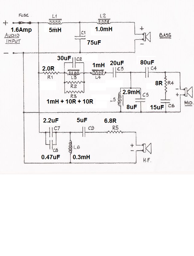
Always worth seeing the schematic, this for a DM2 ver2 IIRC:
I just measured a 10W Ceramic resistor. which is 48mm long. Cost about a pound.
You only replace if the measurement is wrong, IMO.
Might be worth reflowing the solder if it has run hot.
Galu is on the money. Only those old Blue and Red NP Electrolytics might be giving trouble after so many years. Good old speaker, that one.
Last edited:
If you want to stick with the B&W sound, they've gone from generics to 100% Mundorf caps. In the mid-price speakers they use a lot of Mundorf MKP capacitors.
Sorry, I should have been more clear. This is based on pictures of modern B&W crossover. I should not have claimed complete knowledge of all models in all cases. 🙂
Thanks for the schematic Steve!!
Agree that you don't "need" to replace anything. I also think that with any speaker if you can do a full speaker analysis, especially stuff from the 1990's or earlier, you are better off. Never know when you are rebuilding a bad design to start with.
My recommendations were from the perspective of some one wanting to upgrade for fun. 🙂
In the schematic, C1/C3/C4 are all caps that should be measured for ESR before replacing, but I've heard good things about replacing the 2nd order cap on a woofer (C1) so I wouldn't say don't do it... but do so carefully and see what happens. 🙂
I'm learning all sorts today. ��
I've just ordered a new multimeter today that can measure capacitance.... How does that differ from ESR? (Told you I was new to this. ��😉
I was going to test individual components as I remove them, and if they're out of spec replace. Would it be better to replace the big old Capacitors with a modern equivalent? Also the modern equivalents I've seen so far have been much smaller, is that a problem?
Many thanks for all your input everyone.
Capacitance and ESR...
Think of a battery such as a AA or PP3. It can be exhausted in that it can not deliver much current and yet still read a reasonable voltage. In those terms a battery is a like a 'perfect' voltage source in series with a resistor. When the battery is new the resistor is low in value and the battery can deliver current. As the battery wears the internal resistance increase and so the battery can not deliver much current. The driving voltage source is still the correct value (1.5 or 9 volts in this example) but the terminal voltage at the end of the resistor falls as soon as you load the battery.
The cap may still read like its marked value for capacitance and yet have a high ESR. That is a little like saying the cap is a perfect cap but now in series with a resistance. That failure mode is fairly common in electrolytic caps, particularly highly stressed ones in applications like switching power supplies and the like.
Capacitance and ESR...
Think of a battery such as a AA or PP3. It can be exhausted in that it can not deliver much current and yet still read a reasonable voltage. In those terms a battery is a like a 'perfect' voltage source in series with a resistor. When the battery is new the resistor is low in value and the battery can deliver current. As the battery wears the internal resistance increase and so the battery can not deliver much current. The driving voltage source is still the correct value (1.5 or 9 volts in this example) but the terminal voltage at the end of the resistor falls as soon as you load the battery.
The cap may still read like its marked value for capacitance and yet have a high ESR. That is a little like saying the cap is a perfect cap but now in series with a resistance. That failure mode is fairly common in electrolytic caps, particularly highly stressed ones in applications like switching power supplies and the like.
Thats a brilliant analogy, made it nice and easy to understand. So ideally I need an ESR test meter?
I think maybe we agonise over ESR in NP Electrolytics too much. Can't make THAT much difference, can it? ESR is usually about half an ohm for electrolytics. Means they heat up a bit. 🙂
You might run into trouble replacing them with polypropylene types, which are HUGE.
Those Mundorf NP Electrolytics look alright. I have used them. Physically bigger is always better even with NPE types. More heat capacity.
Where people have gone to the expense of using polypropylene types, for all the size problems, they generally thought the sound was better. I think we worry too much sometimes.
Well... ESR meters have their uses I suppose.
One problem would be knowing what to expect for a good cap of the type you are measuring although any obvious major problem would show with an ESR reading.
Just looking for any info for you:
Avnet: Quality Electronic Components & Services
Typical ballpark ESR values vs capacitance is shown in a couple of posts here:
ESR Values for Electrolytic Caps - Page 1
Typical ballpark ESR values vs capacitance is shown in a couple of posts here:
ESR Values for Electrolytic Caps - Page 1
Jeez.... Just glimpsed through that and it's mind blowing. Sounds like the ESR test meters can only tell half the story... Sometimes.
A test meter can only tell you what the ESR of your 40 year old capacitor is today and not what it was 40 years ago!Sounds like the ESR test meters can only tell half the story... Sometimes.
Steve is on the money this time, I would not agonise over ESR, just replace with the likes of the Mundorfs referred to earlier,
P.S. Modern electrolytics are generally much smaller than those manufactured 40 years ago. I wouldn't agonise over size either. On the plus side, if you have to parallel capacitors to achieve the required capacitance, a smaller physical size will be most helpful when it comes to squeezing the combinations into the available space on the board!
Thanks for the tips Erik, much appreciated.
Yep. This is the "breakdown voltage." That is, any voltage higher than this will cause the cap to fail, possibly with a short.
No, now you are just willy nilly replacing parts. Stick to within 5% or less of the originals. Closer is better.
Use Mills 12 watts. Inexpensive, small, sound very good. Leave them an air gap including to the board to ensure they stay frosty.
The R is the decimal point in the resistance. 10R = 10 Ohms. 6R8 = 6.8 Ohms and so on.
If you want to stick with the B&W sound, they've gone from generics to 100% Mundorf caps. In the mid-price speakers they use a lot of Mundorf MKP capacitors.
The last thing I want to point out is be careful replacing big electrolytic caps. The ESR (Equivalent Series Resistance) is typically quite high, and changes to them without additional series resistance can have unexpected consequences.
If you can afford Dayton DATS I encourage you to measure the whole speaker's impedance before you do any work (drivers in cabinet), as well as the ESR of any caps you replace. If it is too expensive, you can use Room EQ Wizard to measure ESR with a jig.
Measuring the impedance before hand will give yo an easy diagnostic tool. While there, measure the impedance of the drivers in cabinet. This will let you do impedance and transfer function (i.e. voltage) simulations (but not acoustical) using XSim.
Thanks very much for the advice Galu, I was starting to fret over the "ESR" thing.A test meter can only tell you what the ESR of your 40 year old capacitor is today and not what it was 40 years ago!
Steve is on the money this time, I would not agonise over ESR, just replace with the likes of the Mundorfs referred to earlier,
P.S. Modern electrolytics are generally much smaller than those manufactured 40 years ago. I wouldn't agonise over size either. On the plus side, if you have to parallel capacitors to achieve the required capacitance, a smaller physical size will be most helpful when it comes to squeezing the combinations into the available space on the board!
Had some great advice from this forum today... Thanks very much everyone.
I did look at those ESR Capacitor links, and I immediately spotted that Rubicon, Nichicon and Elna, and the like, make primarily Polar Electrolytics for Electronic Amplifiers. These are very different animals from our Audio Non-Polars. They are smaller, for one thing.
You might do well to make some notes on what you have here, and write down voltages and dimensions and seek like for like:
That bass capacitor C1, for instance will get quite highly stressed. Lot of power at low frequencies. C5 and C2 are in a very precise resonant circuit and might be working hard and seeing high voltage too.
B&W are highly competent, and will have chosen values carefully so as not to let the smoke out. In engineering you always try and anticipate the worst, while keeping costs down.
Another source of various NPE types here: ClarityCap Solen & Alcap capacitors, audio components for loudspeaker crossovers.
Be interested to know which resistor got hot. Sometimes manufacturers use them as a fuse.
I did look at those ESR Capacitor links, and I immediately spotted that Rubicon, Nichicon and Elna, and the like, make primarily Polar Electrolytics for Electronic Amplifiers. These are very different animals from our Audio Non-Polars. They are smaller, for one thing.
You might do well to make some notes on what you have here, and write down voltages and dimensions and seek like for like:
That bass capacitor C1, for instance will get quite highly stressed. Lot of power at low frequencies. C5 and C2 are in a very precise resonant circuit and might be working hard and seeing high voltage too.
B&W are highly competent, and will have chosen values carefully so as not to let the smoke out. In engineering you always try and anticipate the worst, while keeping costs down.
Another source of various NPE types here: ClarityCap Solen & Alcap capacitors, audio components for loudspeaker crossovers.
Be interested to know which resistor got hot. Sometimes manufacturers use them as a fuse.
I noticed that most, if not all of the Caps I require are reversible.
I've just checked my PCB and the resistor that heated up is on another board.... I'm also refurbing a pair of 1987 B&W Concept 90 speakers. I'll get a picture of that at some point today.
I've made some notes and will have a scout round on the link you sent me to try and match these components up.
Thanks for the links and advice Steve. 👍
I might be being overly prissy, but even amongst Non-Polar types there are different types:
Standard 12uF 50V:
Alcap 12.00uF 50V DC Electrolytic Capacitor non-polarised Standard series from Falcon Acoustics, The Leading Supplier of DIY Hifi Components.
Standard 12uF 100V:
Alcap 12.00uF 100V DC High Power Electrolytic Capacitor non-polarised series from Falcon Acoustics, The Leading Supplier of DIY Hifi Components
Low Loss 12uF 100V:
Alcap 12.00uF Low Loss 100VDC Electrolytic Capacitor - Alcap Capacitors Low Loss 50V/100V - Alcap ClarityCap Solen Capacitors
They get bigger with higher rating, and more expensive.
- Home
- Loudspeakers
- Multi-Way
- Bowers & Wilkins DM2 Series ii Rebuild