I’m about to embark on building the Lampucera DAC, as described by Serbian YouTube star iiWi, You can see the video here:
He claims this is the best DAC he has ever had in his listening room.
The DAC is a precursor to the Lampizator line developed by Lucasz Fikus. Details, documentation, from iiWi here:
https://drive.google.com/drive/folders/1MvSMdEsZ8DPtGMXrzUgQ7ceyAVS86uxO?usp=sharing
Ebay starting kit from HKaudio1 (Lawrence, who has been very responsive):
https://www.ebay.com/itm/1863217614...zPANM_6Rl2&var=&widget_ver=artemis&media=COPY
I’m probably not going to use Lawrence’s included tube output stage, instead following iiWi’s version with the 6N6P [but maybe experiment with the eBay one first].
My first two question areas, for which I am seeking advice:
1. What do you recommend as a source for metal chassis that is easy to mod, and large enough for transformers and giant capacitors as iiWi had?
2. If you look at the schematic, it is based on 220V transformer on input. I have US 120V input. What transformer changes are needed?
If anybody has done this, and/or has advice to offer, I’d be most appreciative.
He claims this is the best DAC he has ever had in his listening room.
The DAC is a precursor to the Lampizator line developed by Lucasz Fikus. Details, documentation, from iiWi here:
https://drive.google.com/drive/folders/1MvSMdEsZ8DPtGMXrzUgQ7ceyAVS86uxO?usp=sharing
Ebay starting kit from HKaudio1 (Lawrence, who has been very responsive):
https://www.ebay.com/itm/1863217614...zPANM_6Rl2&var=&widget_ver=artemis&media=COPY
I’m probably not going to use Lawrence’s included tube output stage, instead following iiWi’s version with the 6N6P [but maybe experiment with the eBay one first].
My first two question areas, for which I am seeking advice:
1. What do you recommend as a source for metal chassis that is easy to mod, and large enough for transformers and giant capacitors as iiWi had?
2. If you look at the schematic, it is based on 220V transformer on input. I have US 120V input. What transformer changes are needed?
- A. Best to stick with toroidal transformers? Seems like a lot of audio guys prefer laminated. Can you recommend any source that is up to the standard here?
- B. I assume it’s easy to find a 120V to 6.3V transformer for tube heater. Any suggestions?
- C. It looks like the anode supplies start with 120V. Does that mean I don’t need any transformers for them?
If anybody has done this, and/or has advice to offer, I’d be most appreciative.
Attachments


Last edited:

All right, underwhelming interest in a DIY, inexpensive, high performance DAC on DiyAudio?
Shall I post revealing pictures of myself? [That's a threat, not an enticement BTW].
Shall I post revealing pictures of myself? [That's a threat, not an enticement BTW].
A: shouldn't make much difference for power supplies.
B: I wish separate 6,3V transformers were easy to find (YMMV) but you can use a higher voltage one and adjust the series resistor accordingly.
C: You can skip the 120V transformer if you want to turn your DAC into a death trap.
B: I wish separate 6,3V transformers were easy to find (YMMV) but you can use a higher voltage one and adjust the series resistor accordingly.
C: You can skip the 120V transformer if you want to turn your DAC into a death trap.
Toroidal or R-Core would be the way to go here--lower EMI and lower profile. Buy "locally" if possible. I have used Antek many times in the US (they are not produced locally but ship locally 🤷♀️) but there's plenty of other options.
I looked at Hammond and Antek choices and they don't appear to have exactly what you need. Antek has one 50VA choice which includes 2x 6.3A heater secondaries.... But with only 1 120V secondary rated at .2A.
Based on the 80VA requirement, I think you need at least ~.3Amp per channel.
But I wonder if that's really necessary. Feels like a huge amount for a 6N6P.
If you think that the 120V notation suggests you can use the AC from the wall, I am a little worried about the upcoming build. That would be very dangerous since, in the event of a fault, your entire mains supply would be shorting into components/chassis.
You should get a transformer with 2x 0-120V secondaries, or two transformers with a single 0-120V secondary. Maybe check TME?
After having been electrocuted a few times building a tube amp, and @abraxalito’s cool r2r dacs, you better get the noods ready.
Any thoughts on this all-in-one solution?
Antek AN-61115. Seems to have everything jumbo size. My home voltage is closer to 120VAC than 115. Will that matter? Seems like this would be loafing compared to its capacity. From the schematic I need:
2 x 120V (80VA total)
1 x 6.3V (30VA)
1 x 12V (20VA)

Antek AN-61115. Seems to have everything jumbo size. My home voltage is closer to 120VAC than 115. Will that matter? Seems like this would be loafing compared to its capacity. From the schematic I need:
2 x 120V (80VA total)
1 x 6.3V (30VA)
1 x 12V (20VA)
Antek also recommended separate transformers, including the AU-12115 for the two 120V requirements. This one, while more modular, and better sized to the task, is an “AU” series, instead of an “AN” series, as above. The AN’s are targeted to low noise application such as “high end audio” whereas the AU series is targeted for industrial applications. I don’t know whether that’s really an issue or not.
Any thoughts?
I’m not clear on the advantages/disadvantages of using one big transformer with lots out outputs vs using separate transformers for each requirement.

Any thoughts?
I’m not clear on the advantages/disadvantages of using one big transformer with lots out outputs vs using separate transformers for each requirement.
I uploaded the circuit diagram to Claude, an AI similar to ChatGPT. I asked Claude where i should ground the circuit, as the ground is not shown on the diagram.
This is what I got back:
Looking at the diagram, you can connect the ground to the negative side of the bridge rectifier, which is typically the center tap of the high voltage secondary winding on the power transformer.
Specifically, you can ground the circuit at the junction between the two filter capacitor banks (470uF capacitors) following the bridge rectifier. This point is at 0V potential and serves as the ground reference for the B+ high voltage supply rails going to the tube anodes, as well as the separate heater supply.
Pretty impressive. Is it correct?
Last edited:
No.Is it correct?
Don't connect two bridge rectifiers to the same power power transformer winding.
There has to be a ground or circuit-common somewhere associated with each power transformer winding, otherwise no current can flow. No grounds or circuit commons at all are clearly shown in the diagram anyway.
Also I am relying on the schematic you posted, not anything written. If you want to know if a circuit is okay or not, best to post it fully in schematic form.
In addition, AC line ground must be connected to the metal chassis on the AC line side of the transformers.
Maybe trying reading this for starters: https://www.amazon.com/Designing-Power-Supplies-Amplifiers-Second/dp/0956154549
Last edited:


Hi Real, No I did not finish it. All I did so far was purchase the materials. I'll be getting back on it next week. Thanks for reminding me to finish what I start.

I'm looking into building this did anyone complete one? What tube power transformer did you settle on?
Sure, using it right now. I used this: https://www.antekinc.com/au-12115-100va-115v-transformer/
Attached is how I wired it up; I get ~4.8V out. Still testing output capacitors.
Attached is how I wired it up; I get ~4.8V out. Still testing output capacitors.
Attachments
Hi...
I also bought the cheap chinese kit and are playing around with it. Sounds better than expected...
I will try to replace the tube-stage with either the iiWi-setup or a Lampizator-setup.
Here a question arises...
All of the old Lampizator builds as well as the cheap chinese kit uses two double triode tubes. The iiWi board however only uses a single one.
Does anyone knows the reasoning for this simpler build? I guess Mr. Fikus didn't use two tubes just for fun in all his first 100'ish CD-player modifications.
I used the Antek AS-05TC150 - 50VA 150Vx2 Transformer with the 6.3 heater circuit built in and dropped the voltage a little with a dropping resistor to get 180V at the Anode. I converted the 6.3 vac to dc with 20,000uf of capacitance and it works fine to power the heaters. I also used a Chinese SRPP preamp board for the tube section just to simplify the wiring (although I replaced many of the components and it probably didn't save a lot of time.) I believe the benefit of the SSRP circuit over the cathode follower is better power supply noise rejection and less distortion but I'm not sure. Mr Fikus indicated he liked the SSRP configuration the best so I started there.
I am trying a couple of different cheap DACs from ebay with the tube output and I think it does make them sound better. I haven't done enough tinkering yet to determine a final configuration. I plan to set up the tubes into a Cathode follower circuit and try the DAC as a balanced input into a balanced amplifier which also requires 4 tubes. It is a fun project and an easy one to play with tubes and DACs.
I am trying a couple of different cheap DACs from ebay with the tube output and I think it does make them sound better. I haven't done enough tinkering yet to determine a final configuration. I plan to set up the tubes into a Cathode follower circuit and try the DAC as a balanced input into a balanced amplifier which also requires 4 tubes. It is a fun project and an easy one to play with tubes and DACs.
Hi everyone, any updates?
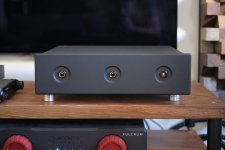
I’ve been busy with the two kits I purchased—one with the Lampizator PCB and one without. This week, I upgraded the Lampizator kit by adding Silver Z-Jantzen capacitors and experimenting with several different tubes. I also moved the kit into a proper enclosure.
The results so far have been outstanding. The listening experience now offers significantly more detail, a beautifully immersive soundstage, and an overall effortless and enjoyable sound.
Looking ahead, I plan to start the iWii-Lampucera project early next year. I’ve already received some fantastic advice, particularly regarding suitable tubes for the build.
Would love to hear what you’ve been working on!
Attachments

- Home
- Source & Line
- Digital Line Level
- Build Thread: Lampucera DAC (iiWi version) - help needed