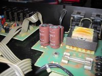
i figured i throw the question up here , when i turn on all the power switches in my system i would get an audible swelling hum , similar to inrush current at 60hz which would stop after a second , almost as if when a cap would fill up it would stop . i narrowed the source down to the carver C-2 . the tone, swelling to a stop. is unaffected by source selection or volume only to be stopped by the mute switch during power on .. i proceeded to replace the 4 caps on the power supply board with Elna audio specific ones , as well as 2 power resistors which looked discolored on the preamp board.
after replacement the preamp sounds absolutely amazing !! night an day difference, BUT THE SWELLING HUM STILL OCCURS
WHAT DO YOU THINK? OPINIONS?
after replacement the preamp sounds absolutely amazing !! night an day difference, BUT THE SWELLING HUM STILL OCCURS
WHAT DO YOU THINK? OPINIONS?
Attachments


Not quite sure what you mean. Are you saying the hum is on the preamp output and that it gets amplified by the rest of the system ? If so then you need to test the preamp in isolation initially with nothing else connected. Scope ? to check the output and rails.
thanks for suggestions.
hum is most certainly on the preamp output( for the second its there).
yes i do have a scope. ill test the output and rails.
hum is most certainly on the preamp output( for the second its there).
yes i do have a scope. ill test the output and rails.
sorry for the crude description but ..
measuring audio out:
with the audio out connected to the scope measuring DC theres a massive sag in the line when the hum swell happens showing increasing AC then a linear peak , then it stops. and when you swap it to AC that same negative sag happens as if theres a negative offset that grows till it pops(haha). this is regardless of channel measured and input selection has no differing effects , however, when the volume is fully off its as if the effect worsens but the swell hum occurs at any volume setting
testing output of power supply :
withe the scope on ac you can see a slight positive rise of the rails during the swell , DC showed no effects . with a multimeter on the rails it showed +/- 14 (give or take a few millivolts ) then it increases to a hair over 15 during the swell and stabilizes there after.
really if it is the supply , the only thing left is the 4 rec diodes , and 4 resistors which show no visual signs of being fried . if theres ac coming through its probably those diodes i guess, since the caps are brand new .
what do you think?
Hi
Are you usung the C2 in 220 or 115v mode.
I have found that the 220 volt transformer setting was troublesome on a couple of c2's whereas the 115v setting works without trouble. Do you have a 240/115v transformer to try the pre in 115v setting?
I have never investigated to try and find out why this is as I have always used them in 115v mode with a small (125va ) 240/115v transformer.
Don
By the way I found it worth while to change the 2 electrolytics that are in the C2's signal path for new 105 degree versions.
If anything is amiss with the diodes it would show on the scope and its also really difficult to visualise exactly what you are seeing on the scope tbh.
OK... the audio outputs should show zero hum under all conditions. AC/DC coupling of the scope might give some anomalies in absolute levels (DC shift/drift) depending how the preamp output is configured... for example if its a 100uf coupling cap and a 470k ground referencing resistor on the output then the settling time is long. Or it might be DC coupled... its an unknown.
So if you are seeing hum the clues are in the frequency... is it line or twice line, eg50/60 Hz or 100/120 hz ?
Its strange that the rails drift in voltage as much as they do. 14 volts rising to just over 15 implies poor regulation or a problem.
Useful info Don. Maybe there is insufficient voltage headroom across the regs in the problem 220v setting you encountered... only thing I can quickly think of.
the mains here are 120v and thats what it is rated for,
don. what 2 electrolytics are directly in the signal path , there is a fair amount electrolytics on the board and thats something id love to see the results of .do you have a schematic?
don. what 2 electrolytics are directly in the signal path , there is a fair amount electrolytics on the board and thats something id love to see the results of .do you have a schematic?
there is also 2 zener diodes for regulation there across the rails which could be the culprit but show no signs of distress
there is also 2 zener diodes for regulation there across the rails which could be the culprit but show no signs of distress
That sounds like a simple shunt regulator (very good performance). If you scope across each zener (scope AC coupled and on a high sensitivity like 0.1v/div) you should see no ripple.
That sounds like a simple shunt regulator (very good performance). If you scope across each zener (scope AC coupled and on a high sensitivity like 0.1v/div) you should see no ripple.
OK just to sate , if i SEE ripple they are toast? and would this trick work in testing the regular diodes in the supply ? excuse my shear thick-headedness
Not necessarily. If the input voltage to a shunt regulator is to low then you would see ripple. Without seeing a circuit for the whole preamp its all guess work and trying to piece the evidence together. If there is a zener across each rail then that suggests shunt regulation... or they could be for overvolts protection and normally non-conducting, its a possibility without seeing the circuit.
Lets assume they are regulators. You should see no ripple at all across them.
Lets assume they are regulators. You should see no ripple at all across them.
OK just to sate , if i SEE ripple they are toast? and would this trick work in testing the regular diodes in the supply ? excuse my shear thick-headedness
And testing the normal bridge rectifier diodes. You would know if one were faulty by the abnormal looking ripple waveform it would cause. The ripple should look like a sawtooth waveform normally.
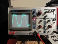
measuring the 2 zeeners one shows a triangle wave at .1 volts/DIV and the other the wave form shoots off the screen and doesn't show up until i switch it to 5 volts/DIV.
the 4 rectifiers all show the same sort of square wave pattern.
whats the opinion ?
the 4 rectifiers all show the same sort of square wave pattern.
whats the opinion ?
Attachments
Without seeing the circuit or having a unit in front of me this is all shooting in the dark.
Lets try something different and something we can be 100% certain of. Use the scope to check the rails at pin 4 and pin 8 of that NE5532 opamp. Have the scope on AC coupling and 0.1 volts/div. It should be absolutely clean.
Lets try something different and something we can be 100% certain of. Use the scope to check the rails at pin 4 and pin 8 of that NE5532 opamp. Have the scope on AC coupling and 0.1 volts/div. It should be absolutely clean.
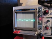
scope on AC coupling and 0.1 volts/div there is a little ripple , but it is unaffected by the big sweeping hum , stays constant from the moment you turn it on .
do you think its normal ?
do you think the vastly different readings from the 2 zeeners denotes they could be toast ?
if you were going to replace things what would you try next?
do you think its normal ?
do you think the vastly different readings from the 2 zeeners denotes they could be toast ?
if you were going to replace things what would you try next?
Attachments
I wouldn't like to say the zeners were faulty without seeing a circuit or having a unit to examine to see what they actually do.
You look to have around 40 mv pk/pk ripple in that scope picture. That's a lot in practice, not expected on a quality product. There are so many twists and turns with something like this. If you connect the scope input and ground probes together you see a straight trace I assume. No noise, no ripple etc. If you keep those leads shorted and then connect them (keeping them shorted) to the working preamp ground do you see the hum appear again ?
I wouldn't replace anything in hope... you need to try and get a handle on something tangible first, something that can be measured as faulty. So lets see if the ripple you are seeing is real or an artefact of the scope/connection/measurement method.
yes the trace is clean when shorted . does working ground mean, the ground of the power supply or can that be any ground on the preamp ?
Good question. It should really be a signal ground (such as the output sockets) because "grounds" around the reservoir caps will carry large half cycle charging currents and that develops a noticeable voltage across wiring and print.
So if you connect the scope ground to a signal ground and then touch the scope input to that ground, is the trace still clean. If not its an artefact of the measurement set up such as a ground loop etc.
Its a tough one to diagnose at a distance. Even if there is ripple on the supplies, the circuitry (certainly opamp based circuitry) would reject that noise anyway. It would be much easier with a circuit 🙂
- Status
- Not open for further replies.
- Home
- Source & Line
- Analog Line Level
- carver C-2 pre hum?