Greetings DIYA members
A while ago a friend gave me an empty Proton D1200 with all the internals removed. These are quite a good chassis with very nice looking VU meters so I've decided to refit it with DIY modules. A new chassis and meters would easily cost a few hundred $ (AUS) - reason enough!
This is a one off project and unlikely to be repeated, unless you have an empty D1200 as well, but I'll be sharing all my ideas, schematics and layouts that may be of use for other member projects.
Naturally there will be discussions along the way.
Cheers
Q
Work so far - the chassis works
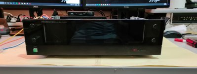
Luckily the chassis is in pretty good condition and the VU meters are still there and working! Members who own a working D1200 may not be happy at this stage but an empty chassis is what it is.
Luckily the chassis is in pretty good condition and the VU meters are still there and working! Members who own a working D1200 may not be happy at this stage but an empty chassis is what it is.
Attachments


Work so far - Power supply
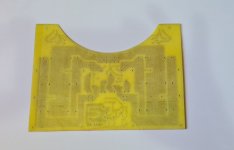
I designed the power supply to fit partway around a large toroid xfmr. Main rails will be +/- 82v with 2 ancillary DC supplies of +10v and +24v. The ancillary supplies will power the DC protect ccts, the VU meters and backlighting plus the 3 level LEDs (0db +3db +6dB).
Soft start cct is also on board. This one is straight from Elektor with some modification - simple as and works a treat.
The amp should deliver around 320 watts per channel into 8.
A couple of adjustments on the PCB where exposure / etching didn't work that well. DIY rules apply.
Attachments

Last edited:


Work so far - a quick check before the xfmr.
A quick review before I disassemble again to fit the transformer. I sort of plan as I go....
I rewound a toroid that I found in old equipment. I keep saying to myself I'm never winding a toroid again.
A quick review before I disassemble again to fit the transformer. I sort of plan as I go....
I rewound a toroid that I found in old equipment. I keep saying to myself I'm never winding a toroid again.
Attachments


No to the amp modules.
This is the schematic that I think I will be going with. I have drafts of it around in other posts and with the help of a few members have arrived at this version.
The PCB's are made so other than some component values, I don't anticipate too many changes. Of course I've been wrong before.
The PCBs have provision for a separate feed to the output stage and this allows for cleaner current delivery to the first few stages. It could also connect the first few stages to slightly higher rails - gaining some efficiency.
Attachments

Last edited:
So where to from here?
I now need to build the amp modules. The amp schematic SIMs rather well but the real world could be different. Hopefully all the research, help and adjustments pay off.
I also have to re-create elements of the original Proton features; the VU drivers and LED power indicators.
I had trouble finding a TA7318P so I purchased a pre-built VU driver PCB to do the job. I also purchased a LB1405 LED VU driver to make my own PCB with. Both of these from Ali-Express so wish me luck.
So unlike the Proton big main board, this will be assembled with several discreet modules. Hope it all fits!
Q
Attachments


Acknowledgements
I want to acknowledge the help by some members that contributed to this amp module. The discussions can be found here; Second Stage. Paralleling transistors ok? and from this post on; Power amp under development.
Cheers
Q
I want to acknowledge the help by some members that contributed to this amp module. The discussions can be found here; Second Stage. Paralleling transistors ok? and from this post on; Power amp under development.
Cheers
Q
Wow. That should really encourage those cones to go in and out.
Ha! Hopefully I wont set fire to anything. Hi Suzy nice to hear from you. I've been following your AEM6000 improvements with great interest. Your stuff is so cool.
Cheers
Q

Hi Quasi,Work so far - Power supply
I designed the power supply to fit partway around a large toroid xfmr. Main rails will be +/- 82v with 2 ancillary DC supplies of +10v and +24v. The ancillary supplies will power the DC protect ccts, the VU meters and backlighting plus the 3 level LEDs (0db +3db +6dB).
Soft start cct is also on board. This one is straight from Elektor with some modification - simple as and works a treat.
The amp should deliver around 320 watts per channel into 8.
A couple of adjustments on the PCB where exposure / etching didn't work that well. DIY rules apply.
I liked what you did with the Proton D1200.
Any idea what are the transformer rating/s of the original Proton D1200. I believe there are two transformers, right? I will appreciate if you can write to me on petruspachis@gmx.de
Thank you.
- Home
- Amplifiers
- Solid State
- Chassis re-fit of a Proton D1200 (not a restoration).