Hi Everyone,
I thought I'd post a few pictures of the power supply I'm building for an F3, and ask a few questions. The overall plan is for two mono amps, powered from a separate PSU to which they will be connected by umbilicals. Boards and various bits and pieces are coming from another diyaudio member, jameshillj. The final design for the amps themselves is still to be determined.
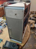
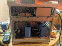
The power supply is going in another Apple computer case, to match the F5 monoblocs from this thread from a few years ago.
https://www.diyaudio.com/forums/pass-labs/285298-building-f5-monoblocks-apple-g5.html
I'm planning to use the F3s together with the F5s in a bi- or tri-amped system. (Which is probably far more than necessary for the small room I listen in, but should be big fun anyhow.)
The transformer is the one I discussed in another thread a couple of months ago:
https://www.diyaudio.com/forums/pass-labs/363450-questions-transformer-markings.html
(Thanks again to everyone who helped out there with advice.) I don't know its exact power rating; it was sold to me as 1000VA but I doubt it. However it weighs about 11 pounds, so it's most likely a fair bit larger than needed for an F3.
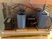
Everything except for the transformer is dual mono. I have fancied trying a CLC supply for a while, so looking around ebay and surplus sites I collected various bits and pieces, and here is the result (so far). The chokes are two Hammond 195J10, 10mH at 10A. The big electrolytics are from a surplus site; Cornell Dubilier 100V, 41,000uF each. I didn't do any very careful calculations of what to use, I just went with what I could find at reasonable prices that looked like fun to try out.
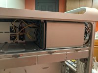
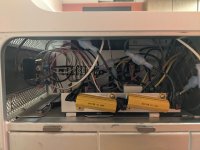
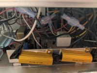
The transformer fits perfectly in the ventilated steel box that the power supply for the computer lived in, which is behind the aluminum cover at top right. All the rest of the AC stuff is to the left; four rectifier bridges at back, on part of what used to support the CD/DVD drive, and in front is a soft-start board (with two big Mills ballast resistors) which uses the schematic from Rod Elliott's ESP site. (The one with an auxiliary 9v transformer.) I have it timed to roughly 1/4 second, and it seems to work very well.
I have two questions for the experts here.
1. Running the supply at approximately what will be full load the output voltage is high; almost exactly 51V. ZM said elsewhere that that was OK for an F3, but I'm not sure whether he meant for the test that the poster was asking about, or whether more generally 51V is OK for the F3. ZM? Anyone?
If the answer is no then I'll have to reduce somehow. Maybe an additional RC filter? There's plenty of space in the case. (I also have another pair of inductors, which would fit in the bays that originally housed the hard drives. It crossed my mind to try CLCLC... just sayin... )
)
2. I have not fitted any snubbers on the rectifier bridges. I took a look at the (very interesting) Quasimodo thread, but I don't have an oscilloscope, and it looks like there is no way to figure out the values without one. Are snubbers going to make much difference here? If yes, then is it better to estimate values, or does someone have any suggestions as to what to use? (There's a thread that lists values people have found for identifiable transformers, but that isn't what I have here.)
Anyway, thanks for any input, and I hope you all enjoy the pictures.
Best
Nigel
I thought I'd post a few pictures of the power supply I'm building for an F3, and ask a few questions. The overall plan is for two mono amps, powered from a separate PSU to which they will be connected by umbilicals. Boards and various bits and pieces are coming from another diyaudio member, jameshillj. The final design for the amps themselves is still to be determined.
The power supply is going in another Apple computer case, to match the F5 monoblocs from this thread from a few years ago.
https://www.diyaudio.com/forums/pass-labs/285298-building-f5-monoblocks-apple-g5.html
I'm planning to use the F3s together with the F5s in a bi- or tri-amped system. (Which is probably far more than necessary for the small room I listen in, but should be big fun anyhow.)
The transformer is the one I discussed in another thread a couple of months ago:
https://www.diyaudio.com/forums/pass-labs/363450-questions-transformer-markings.html
(Thanks again to everyone who helped out there with advice.) I don't know its exact power rating; it was sold to me as 1000VA but I doubt it. However it weighs about 11 pounds, so it's most likely a fair bit larger than needed for an F3.
Everything except for the transformer is dual mono. I have fancied trying a CLC supply for a while, so looking around ebay and surplus sites I collected various bits and pieces, and here is the result (so far). The chokes are two Hammond 195J10, 10mH at 10A. The big electrolytics are from a surplus site; Cornell Dubilier 100V, 41,000uF each. I didn't do any very careful calculations of what to use, I just went with what I could find at reasonable prices that looked like fun to try out.
The transformer fits perfectly in the ventilated steel box that the power supply for the computer lived in, which is behind the aluminum cover at top right. All the rest of the AC stuff is to the left; four rectifier bridges at back, on part of what used to support the CD/DVD drive, and in front is a soft-start board (with two big Mills ballast resistors) which uses the schematic from Rod Elliott's ESP site. (The one with an auxiliary 9v transformer.) I have it timed to roughly 1/4 second, and it seems to work very well.
I have two questions for the experts here.
1. Running the supply at approximately what will be full load the output voltage is high; almost exactly 51V. ZM said elsewhere that that was OK for an F3, but I'm not sure whether he meant for the test that the poster was asking about, or whether more generally 51V is OK for the F3. ZM? Anyone?
If the answer is no then I'll have to reduce somehow. Maybe an additional RC filter? There's plenty of space in the case. (I also have another pair of inductors, which would fit in the bays that originally housed the hard drives. It crossed my mind to try CLCLC... just sayin...
)2. I have not fitted any snubbers on the rectifier bridges. I took a look at the (very interesting) Quasimodo thread, but I don't have an oscilloscope, and it looks like there is no way to figure out the values without one. Are snubbers going to make much difference here? If yes, then is it better to estimate values, or does someone have any suggestions as to what to use? (There's a thread that lists values people have found for identifiable transformers, but that isn't what I have here.)
Anyway, thanks for any input, and I hope you all enjoy the pictures.
Best
Nigel
Attachments
Hi, thanks for the quick responses.
Yes, but wouldn't this also reduce the normal 46V? Just to understand better, what would be the maximum rail voltage for an F3? What's the limniting factor? The Loveltech jfet?
I wondered if that would be the answer from the perspective of the F3 itself, but I've read that one of the reasons for snubber networks is to reduce the noise put back into the mains. Presumably the filtering wouldn't affect that, or did I misunderstand (again)?
Best
Nigel
51V is fine.
There is a cap multiplier on the F3 which will drop the voltage further anyway.
Yes, but wouldn't this also reduce the normal 46V? Just to understand better, what would be the maximum rail voltage for an F3? What's the limniting factor? The Loveltech jfet?
With the mount of power supply filtering you have etc the snubbers won't be necessary
I wondered if that would be the answer from the perspective of the F3 itself, but I've read that one of the reasons for snubber networks is to reduce the noise put back into the mains. Presumably the filtering wouldn't affect that, or did I misunderstand (again)?
Best
Nigel
Hi, thanks for the quick responses.
I wondered if that would be the answer from the perspective of the F3 itself, but I've read that one of the reasons for snubber networks is to reduce the noise put back into the mains. Presumably the filtering wouldn't affect that, or did I misunderstand (again)?
Best
Nigel
You should have mains filtering as standard anyway. So look at how to best do that.
It doesn't hurt to add snubbers if you want, but it won't make any significant improvement with your specific application.
Since nothing is going to get past your power supply + cap multiplier.
Last edited:
Hmmm... I hate to sound dense, but what do you mean by "mains filtering" here? Something built into the amp, or between it and the mains?
If to the amp, then I have a 100nF X2 capacitor across the 120v input to the primary. After the soft start, actually, since that's what Rod Elliott's article recommends, but nonetheless this is its purpose. Is that what you meant by mains filtering? Or something more extensive?
If to the amp, then I have a 100nF X2 capacitor across the 120v input to the primary. After the soft start, actually, since that's what Rod Elliott's article recommends, but nonetheless this is its purpose. Is that what you meant by mains filtering? Or something more extensive?
X caps, y caps, electrostatic shield if you have one on the transformer etc.
You can do better than bare minimum.
Wayne puts x caps across the secondary windings also.
I think it might be 220nF
You can do snubbers.
Basically what I am trying to say is put the most effort into areas that will make the most improvements.
You can do better than bare minimum.
Wayne puts x caps across the secondary windings also.
I think it might be 220nF
You can do snubbers.
Basically what I am trying to say is put the most effort into areas that will make the most improvements.
Last edited:
Basically what I am trying to say is put the most effort into areas that will make the most improvements.
Now *that* makes perfect sense to me.
Thanks for all the input.
Best
Nigel
you're good, as pico sez
Thanks, ZM.
Another thought. As I mentioned above, I have another pair of inductors I picked up, and the hard drive slots are *exactly* the right size to pop them in there. I had been wondering about trying CLCLC, just because it would be easy if I get a few more caps. But it also occurs to me that I could easily try a LCLC, with choke first. I've read elsewhere that this would cause a voltage drop, but I have at least some headroom to spare. Any thoughts?
I'm fiddling around trying to get PSUD to run on my (slightly oddball) Linux system. I'm curious as to what it would tell me. I also have my eye on an old RCA oscilloscope that's sitting unloved in my local Goodwill. It would be nice to try all these options out and measure what happens.
Best
Nigel
be stubborn to try with PSUD, it'll help a ton
I'm working on it.
with L input, do not count on more than 90% of input voltage, at output of filter
Well, since I have about 51V right now, 90% of that would be 46V. Which is spot on for an F3, I believe?
Of course none of this is probably necessary, but it is interesting and fun.
I think the output is 90% of the input RMS voltage. That would make it about 51V/1.3*0.9 = 35V.
Thanks. I dug around on the internet a little and you're quite right. That is too low for what I need.
In any event the same digging around(including here on diyaudio) tells me that the inductors I have are too small for LC or LCLC. Apparently inductance of the choke (in H) should be at least output voltage V divided by current draw I in mA. So if output voltage is to be 46V, and bias current is 1.6A (I can't remember what it is exactly without checking) then I would need around 29mH. This is bigger than I have, so LC or LCLC are out.
No problem. I'm sure CLC will work fine, and CLCLC will be fun to try...
- Home
- Amplifiers
- Pass Labs
- CLC power supply for F3 in Apple computer case