Any source for CCS boards/kits? I've used K&K ones in the past but I'm having a hard time reaching him and he is not responsive on his forum board.
I'm planning on using them on 5687 tubes.
Not skilled enough to create my own.
TIA
I'm planning on using them on 5687 tubes.
Not skilled enough to create my own.
TIA
Thanks!I probably still have some unused pimm ccs boards I had made. I'll check this evening
Another option is Ale's board.
https://www.bartola.co.uk/valves/for-sale/ccs-pcb/
p.s.
BTW building one on prototype board in easy (if you know which end of the soldering iron is hot 🙂 ).

https://www.bartola.co.uk/valves/for-sale/ccs-pcb/
p.s.
BTW building one on prototype board in easy (if you know which end of the soldering iron is hot 🙂 ).
Last edited:

What will be the expected voltage drop on the CCS? I am using a Current Regulator Diode from the range 1N5283...1N5314 (0.22 .... 4.7mA) in an LTP. You can connect two or more different diodes parallel to set the desired current. The dynamic impedance is not too exceptional, but they give the smallest footprint. Attached is the Microsemi data sheet.
Attachments

Have you tried to put jfet or some small smd depletion in the cascade instead of the lower DN2540 or put IXTP08N100D2 instead of the upper DN2540?
I have been using these combinations for years and they are much better than the DN2540 or the classic cascade with them.
I have been using these combinations for years and they are much better than the DN2540 or the classic cascade with them.
Attachments


For those in a similar situation I found kits at Bottlehead, V4lve lover and Bartola. Not all have the transistors needed.
Thanks all.
Thanks all.
I located a schematic from K&K (who's kits have worked well in the past) and the MOSFETs on the BOM.
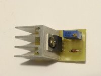
I decided to to buy some perfboard and am planning of creating my own in an effort to learn something
Would someone kindly look over my layout and compare that to the schematic? I left the place for the Rset resistor out for simplicity.
Thanks in advance for the help!


I decided to to buy some perfboard and am planning of creating my own in an effort to learn something
Would someone kindly look over my layout and compare that to the schematic? I left the place for the Rset resistor out for simplicity.
Thanks in advance for the help!
A few things to know when using a CCS:
What is the current?
What is the burden voltage (minimum voltage they can still act as a current source).
What is the maximum voltage they can work at.
A CCS in the cathode of a tube that only has 1V self bias will not work with 90% of all the CCS out there.
You have to know what are the range of voltages that will be across the CCS.
That includes the DC quiescent voltage; and includes the signal level that causes the maximum + and - swings above and below the quiescent voltage.
Failing to follow these rules means that it will not have a constant current.
Wow. I was just trying to duplicate a well known circuit that seems to be working in an identical circuit.
The only spec I know for sure is the current is to be set at 10mA.
Thanks for the input!
The only spec I know for sure is the current is to be set at 10mA.
Thanks for the input!
Because nowadays only high voltage (500-1000V) and enough (0.1 ...3A) current capability depletion MOSFETs available, whichever is good.
https://eu.mouser.com/c/semiconduct...s=1 Channel&package / case=TO-220-3&instock=y
Be aware that CCS working well if enough (30..50V) headroom voltage is available.
CCS also working in cathode if you use enough (30..50V) negative voltage.
https://eu.mouser.com/c/semiconduct...s=1 Channel&package / case=TO-220-3&instock=y
Be aware that CCS working well if enough (30..50V) headroom voltage is available.
CCS also working in cathode if you use enough (30..50V) negative voltage.
- Home
- Amplifiers
- Tubes / Valves
- Constant Current Source