hello , first at all , thanks for all precious informations we can find in the forum.🙂
I hesitate to build new cabinet for my woofer ( Xover = 500 Hz) , in order to reduce vibrations.
I found lot's information about the panel material , thickness , bracing , damping.. but nothing about the constrain we can apply on the panel during the cabinet construction.
Let me give you an example :
Consider we use a bracing , but the size is a little bit bigger ( or smaller) on the middle on each 4 sides , ( 1 mm for example).
So , the panel fixed on the bracing will support a flexion... based on my feeling , the panel frequency will increase.
Do you have any experience about this ? Is there basic theory about this ?
I hope my explanation is clear.
Thanks in advance !
Joel
It took a while to gain an understanding of the question, if I have. I suspect this is the reason some venture to use shelf braces instead of cross braces.
I'm not sure it's always needed. Panel damping picks up where basic bracing leaves off, and it manages concerns about conducted vibrations.. something shelf bracing won't necessarily do.
I'm not sure it's always needed. Panel damping picks up where basic bracing leaves off, and it manages concerns about conducted vibrations.. something shelf bracing won't necessarily do.
Hi , thanks for your answers.
In order to be sure you correctly understand my question , I add a document to show you 2 examples :
1) with batten
2) with bracing.
You will see than on both example : the size is a little bit more important in order to be able to bend the panel.
I 'm sure the frequency will encrease , but I don't know how to quantify this , or if there is an empiric rule.
For my point of view, it's an interresting way to assemble a cabinet because we increase the panel frequency : without increasing the cabinet weight , size , panel thickness , bracing quantity.
Joel
Attachments

Pre-stressing might be the term for what you're describing. You could get the same effect and easier to build with brace L=a-1mm...

This is an extensively braced cabinet, it's made from 3.4mm ply, so is lightweight (1kg for an 8 litres enclosure) but very stiff, giving it a high natural resonance, well about the 250 (approx) Hz frequency of the bass driver. This works really well. Lots of ribs, and braces.

I also think so.Pre-stressing might be the term for what you're describing.
I am no structural engineer, but bending a board (by applying a bending force/pre-stressing) makes it more stiff and thus raises panel resonance frequency.
There's this old figure:
Thanx for posting the Tappan Andersonix: Here is the original, a bit bigger and easier to read.
Basics are that dividing panel into smaller panels pushes the (potential) panel rresonance higher in frequency. As Tappan shows a brace in the long direction is most effective.
A brace is more effective if it braces 4 panles. I also like to place them at “irregular” intervals. I like to place the holes in the brace to serve to break up higher frequency eigenmodes.
Here an over-the-top example,
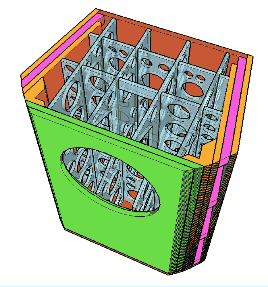
Prestressing panels does not hurt. A brace that is a tiny bit too bit, or GM’s frequent suggestion of a ready rod tightened up just enuff to stress the panels,
dave
Hi , I just find interesting information. About the "musical saw". 🙂
The appliquation and material ( steel vs wood) is completely different , but the theorical approach is the same for my point of view.
Too late today from france to study the document !
https://archive.iypt.org/Sutter_Tomczyk_Singing_saw_finals_IYPT_2001.pdf
The appliquation and material ( steel vs wood) is completely different , but the theorical approach is the same for my point of view.
Too late today from france to study the document !
https://archive.iypt.org/Sutter_Tomczyk_Singing_saw_finals_IYPT_2001.pdf
500hz resistance, looks like it would need a brace every few inches. In steel plate, at least.
It might be better to build without, then measure what needs doing.
It might be better to build without, then measure what needs doing.
Decent plywood or better, and smart design make it doable. A light, stiff material of appropriate thickness gives you a head start. Steel or aluminium would be a good material, but one would need specialized skills.
For a woofer, push-push with 2 drivers makes a dramatic difference. The active reaction force cancelatiion reoves most of the energy going into the enclosure from the miovement of the woofers.
dave
For a woofer, push-push with 2 drivers makes a dramatic difference. The active reaction force cancelatiion reoves most of the energy going into the enclosure from the miovement of the woofers.
dave
To be clear material stiffness doesn't depend much on how an object is stressed (bent), but the stiffness of the object itself depends heavily on its shape and its support - which is why a dome is much more rigid than a flat sheet. Its all about how a small change in shape translates to compression/tension and shearing in the bulk material, and that is a complex function of the shape and how it is fixed to other objects.I am no structural engineer, but bending a board (by applying a bending force/pre-stressing) makes it more stiff and thus raises panel resonance frequency.
For instance a pit-prop that's cemented into floor and ceiling is twice as stiff (against buckling) than one that simply rests against floor and ceiling.
Pre-stressing in the opposite direction would be useful if the load was in one direction, but here the cabinet is breathing both in and out. So build it from cheap surplus ply and add bracing as needed later.
Cross lower than 500Hz! With an active xo, right?
Cross lower than 500Hz! With an active xo, right?
500hz is the highest I have seen a separate woofer crossed over. The mission cube system, which wasn't made for music.
The maths to calculate a solution, are probably making a super computer sweat. What modelling programs there are, perhaps work by example rather than exacting material science.
Just looking quickly at this, I see a 500hz wave is 68cm long. However proportions of this dimension will align, such as a half wave, who might have to ripple along twice, but will still be at the same point at the right time, even though the route was different. That route might be slowed if it's a hot day, or you had to swim. This is propagation delay. Then there is the excitation of the board, not just it's density, but it's form offering different stiffness. Then we have to support it. If it was round, then a central support has taken the diameter and halved it. From the center, to the edge, is the same distance (think wavelenghths) to the edge, in and direction. If you move the support away from the middle, you no longer have a couple of dominant sizes, but an array of distances from support to edge. Then if we start adding boards to our board, that all have their own resonances, the picture starts to get complicated. Maybe calculable, but just how many computations is that. Each effecting the calculations you thought you were done with.
Today we are kinda seeing elastomers used in bracing. Mostly it's in adhesives, but offers ways to hold a panel, dampening low frequency energy, without being stiff enough to ring at higher frequencies. I'm not sure what we can use, that stiffens at lower frequencies instead of higher one's. As we see in the bass bin vs custard videos.
Sometimes just going a bit excessive and seeing how it turns out can work

A lower cross would really help the project.
Edit: Pick your work space. These were perfect before a night in the garage awaiting some sealant. Look how the side sticks out a couple of mm from the baffle. A baffle it is glued to. That couple of mm has risen from nowhere. The edge expanded out, yet seems no softer, of held back by being glued to the 36mm of baffle. No gaps, no failed joints, even now, It looks impossible. Be careful..
The maths to calculate a solution, are probably making a super computer sweat. What modelling programs there are, perhaps work by example rather than exacting material science.
Just looking quickly at this, I see a 500hz wave is 68cm long. However proportions of this dimension will align, such as a half wave, who might have to ripple along twice, but will still be at the same point at the right time, even though the route was different. That route might be slowed if it's a hot day, or you had to swim. This is propagation delay. Then there is the excitation of the board, not just it's density, but it's form offering different stiffness. Then we have to support it. If it was round, then a central support has taken the diameter and halved it. From the center, to the edge, is the same distance (think wavelenghths) to the edge, in and direction. If you move the support away from the middle, you no longer have a couple of dominant sizes, but an array of distances from support to edge. Then if we start adding boards to our board, that all have their own resonances, the picture starts to get complicated. Maybe calculable, but just how many computations is that. Each effecting the calculations you thought you were done with.
Today we are kinda seeing elastomers used in bracing. Mostly it's in adhesives, but offers ways to hold a panel, dampening low frequency energy, without being stiff enough to ring at higher frequencies. I'm not sure what we can use, that stiffens at lower frequencies instead of higher one's. As we see in the bass bin vs custard videos.
Sometimes just going a bit excessive and seeing how it turns out can work
A lower cross would really help the project.
Edit: Pick your work space. These were perfect before a night in the garage awaiting some sealant. Look how the side sticks out a couple of mm from the baffle. A baffle it is glued to. That couple of mm has risen from nowhere. The edge expanded out, yet seems no softer, of held back by being glued to the 36mm of baffle. No gaps, no failed joints, even now, It looks impossible. Be careful..
Last edited:
- Home
- Design & Build
- Construction Tips
- constrain the panel in order to increase natural frequency