Hello gentlemen, for some time I have wanted to build an amplifier with darlington transistors, on the web I have found few diagrams and the one that has attracted my attention the most is this because it has components that I easily get in my country (I live the third world) I was wondering what they think of the scheme.
Attachments

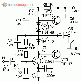
The diagram is rather conventional.
On PA forum, a shop owner in Greece reported how many service jobs he took in on darlington based amps by contrast with amps with separate drivers and output transistors. He found the darlington amps great moneymakers for a service shop whose customers were mainly resort bars & taverns. He theorized it may be because the driver shares the heat of the output transistor and participates in the thermal runaway that can result.
Notice in 99% of the separate driver transistor amps, the drivers are not installed on the same heat sink as the output transistors. A lesson learned perhaps?
However as long as you never get one hot, what thermal problems can there be? Bars & tavernas do run their systems loud.
As this is a direct coupled amp, one bad solder joint can cause DC on the speaker and destroy it. Best invest in a DC protection board if your speaker cost more than $4.
Enjoy your experiment.
Last edited:
Jo is right, no protection against shorts/overcurrent or DC on output.
Bandwidth wasted by the second 1k on bottom.
Bandwidth wasted by the second 1k on bottom.
The BD140 current source needs a couple hundred ohm base stopper resistor, otherwise you *will* be putting DC to the speaker the first time you clip it. Without the resistor it WILL latch up, regardless of using darlingtons or discrete outputs.
These darlington amps like to blow up a lot because most of the transistor choices are just too weak, even if short circuit protection were added. Blasting a 4 ohm load will take out the TIP142/147. You’ll have a lot harder time blowing up MJ11015/6’s or the Sanken D2083/B1383. But you might have a hard time getting them, too.
These darlington amps like to blow up a lot because most of the transistor choices are just too weak, even if short circuit protection were added. Blasting a 4 ohm load will take out the TIP142/147. You’ll have a lot harder time blowing up MJ11015/6’s or the Sanken D2083/B1383. But you might have a hard time getting them, too.
Darlington power transistors include built in resistors so you have to live with the those values. The resistors are important because they speed up the device turn-off. Better amps use cross coupling which is not possible with a 3 wire device. I don't know of a 4 wire Darlington but that would solve this issue. TIP14x also have a resistor on the driver which is great when used to drive a ~relay from logic chips but not in an analog amplifier.
Probably the real problem is that they are a short-cut that attracts beginners, who are also likely to abuse the SOA of the transistor. +/-42V on TIP140x is a good example. +/-25V is a more realistic limit.
Probably the real problem is that they are a short-cut that attracts beginners, who are also likely to abuse the SOA of the transistor. +/-42V on TIP140x is a good example. +/-25V is a more realistic limit.
Last edited:
Hmmm.... 42V power supply rails with BD139/140 voltage amplifiers? I think that is asking for trouble but there are other cheap and popular types like 2SD669A/2SB649A or even 2SD667A/2SB647A that should be more reliable.
Otherwise, I suggest DC supply voltages of only +/- 35Vmax. would be safer with a properly rated power supply, or use higher voltage rated transistors, such that none of the voltage ratings can be exceeded in situations where there are power line variations, surges and spikes yet the amplifier still has enough current to drive 4R or 8R speakers to their ratings, as required.
Otherwise, I suggest DC supply voltages of only +/- 35Vmax. would be safer with a properly rated power supply, or use higher voltage rated transistors, such that none of the voltage ratings can be exceeded in situations where there are power line variations, surges and spikes yet the amplifier still has enough current to drive 4R or 8R speakers to their ratings, as required.
Last edited:
with + -42 V supply voltage 1 pair of TIP transistors - only suitable for 8 ohm load. BD transistors + -40V are already on dangerous limits.
Better build tested circuit with testetd PCB layout and created by the famous NP.
Transistors can also be used in a variety of options.
AB100 Class AB Power Amplifier
Better build tested circuit with testetd PCB layout and created by the famous NP.
Transistors can also be used in a variety of options.
AB100 Class AB Power Amplifier
That’s only 1/4 of the power, on a single supply. I’d still add the emitter resistors to the output pair. Use the TIP14x’s and it might even survive w/o SOA protection (saggy supply with a small transformer, large emitter resistors, and the ESR of the output cap are your friends here). A 1 ohm emitter resistor goes a long way when it’s your only current limiting mechanism.
There is unfortunately no easy fool-proof-no-math-one-size-fits-all circuit you can “add” to properly do short circuit/ SOA protection like there is for DC protection (IC plus relay). You can make it quite simple (a flat limit of vbe divided by the emitter resistor) but that’s only effective on the smallest of amplifiers. Gotta go beyond that if yore using much more than about 25 volt single supply, or willing to use complete overkill for your output devices (ie six c5200’s in parallel for miserable 40 volt rails).
There is unfortunately no easy fool-proof-no-math-one-size-fits-all circuit you can “add” to properly do short circuit/ SOA protection like there is for DC protection (IC plus relay). You can make it quite simple (a flat limit of vbe divided by the emitter resistor) but that’s only effective on the smallest of amplifiers. Gotta go beyond that if yore using much more than about 25 volt single supply, or willing to use complete overkill for your output devices (ie six c5200’s in parallel for miserable 40 volt rails).
Member
Joined 2009
Paid Member
Despite the general distaste for Darlington output amps I can say that after more than a decade in this hobby and many DIY amps, the amp that has been consistently used most days with excellent sound is a Darlington amp. It uses high performance Sanken devices that I can recommend to you.
I started with a commercial amp which I simulated in Spice and then identified key topology changes to a design of my own. I did this with two different amps from the same manufacturer and both times with good results. My modifications resulted in very good performance. Reliability of these amps has, obviously, been good but I don’t run a disco!
Details here:
TGM6 - modified Pioneer HT amplifier
“High performance Sanken devices” - translation: “if you don’t have a credit card and Digikey doesn’t ship to your address you’re F****”. One big reason people are drawn to “designs” like this.
What’s needed is a 100-watt-4-ohm design that can be built out of ONLY generic devices (and fakes) that a) won’t blow up, and b) won’t oscillate with the most commonly used devices.
It would be nice if we could get to 200 watts, 8 ohm, without exploding at 4, but that really would be asking for too much.
If you “run a disco” you need real amplifiers, period.
- Home
- Amplifiers
- Solid State
- Darlington Amplifier