I'm working on a portable amp project and am wondering about the feasibility of using a dc voltage multiplier so that I might reduce the size (and cost) of the battery pack.
The most recent amp I've built is a class D unit using the TPA3110D2 from TI. On other portable stereo applications, I've used pretty large battery packs (i.e. 12 NiMH cells to generate 14.4v) But for this next project I'd like to go a bit smaller.
The TPA3110D2 can be powered by as little as 8V (and as much as 26V).
What I'd like to try would be a 3 cell (3.6V) or 4 cell (4.8V) pack, so that the battery could be recharged from a USB port.
The problem here is getting the voltage up to the minimum 8 volts required by the amp chip. Also, if I recall correctly, the chip drew around 0.5 amps when set to a normal listening volume. What's the simplest solution? Just browsing around digikey revealed several dc-dc step-up converters and charge pumps, etc. The only problem was that they were all rated for very low current application (i.e. tens to a few hundred milliamps).
I realize that using a smaller pack and multiplying the voltage will result in limited usable time per charge, but it seems like it might be worth a shot. The 12 cell NiMH packs are great for battery-life, but they're a little big and expensive.
Thanks!
-Chad
In general all batteries offer cheaper power when using one larger cell
In general all batteries offer more energy /unit volume and /unit weight when using one larger cell.
The result of that, is that using a DC to DC converter chip to generate 3V/6V/9Vdc from a 1.5V single cell is usually lighter and smaller and ends up cheaper to operate.
In general all batteries offer more energy /unit volume and /unit weight when using one larger cell.
The result of that, is that using a DC to DC converter chip to generate 3V/6V/9Vdc from a 1.5V single cell is usually lighter and smaller and ends up cheaper to operate.
Thanks Andrew
That's definitely a direction I would like to explore. Any thoughts on a simple voltage multiplier circuit or IC that could provide enough current to power the TPA3110D2?
Thanks again,
Chad
That's definitely a direction I would like to explore. Any thoughts on a simple voltage multiplier circuit or IC that could provide enough current to power the TPA3110D2?
Thanks again,
Chad
Maxim makes some step-up DC DC ICs for laptop displays. I'm thinking of giving the MAX17112 a shot, as it's in stock at Digikey.
datasheet here:
http://datasheets.maxim-ic.com/en/ds/MAX17112.pdf
datasheet here:
http://datasheets.maxim-ic.com/en/ds/MAX17112.pdf
There are almost too many to count. I would use either Linear Technolgy or National Semiconductor stuff. If you go to national.com and select the Webench on-line app, you can put in the specs and it will give you a list of appropriate chips and design a complete power supply automatically, for the one you select. At linear.com, the free LTspice used to do the same thing (and still might), by selecting File then Switch Selector Guide. Both sites have TONS of application notes with DC-to-DC converter (aka switchmode power supply) schematics. And there are many, many chips that can easily do 5 to 10 amps. So your current and power requirement should be absolutely no problem, in that sense.
I need a simple linear voltage multiplier with 10x (20db) gain for an input signal of 0-5VDC, <10ma out (is OK). I would prefer to just buy something. I want to amplify a variable voltage 0-5vdc to 0-50vdc. I need suggestions. Thanks.
MPJA dot com -- boost converters https://www.mpja.com/DC_DC-Converters/products/42/
0 - 50 is going to be tough for an inexpensive converter. You might try the Analog Devices or Texas Instruments search engine for a one chip solution with a development board. There are a lot of 0-60V one chip designs on the Analog website.
0 - 50 is going to be tough for an inexpensive converter. You might try the Analog Devices or Texas Instruments search engine for a one chip solution with a development board. There are a lot of 0-60V one chip designs on the Analog website.
I am connecting a 0-10V analog output (+/-.0005v) from a Galil motion controller to a cheap 0-100v digital read out and representing an angle where zero volts = 0 degrees, 1 volt = 1 degree etc. - up to 45 degrees. I will only be allowing 0-45deg (0 to 45v) on the display. I can program that setting. But I only have 0-10v DC to play with. With a 5x multiplier I get 0-50V to the meter (and again will limit it to 0-45). I can use a any gain >=4.5. But the greater the gain, the lower the resolution. So 0-5v in and 0-60v out will work, just change my scale. I saw the 10-60v. When I put 0v in I want 0v out, 1vin=10vout, etc. The span of that converter is right (50v range), is there a way to bias offset that output to 0-50v? Thanks. Love those Cleveland Indians.
The big problem I see is the power supply needed, the 0 to 5 volt into 0 to 50 volts could be the easy bit if you use a high voltage opamp configured for whatever gain you want. That is the simple part.
The problem is that to get to +50 volts output swing needs a supply a bit over that together with a lower voltage negative rail of even just a few volts (to allow the opamp to get to a true zero output).
There are opamps available that have a total supply voltage rating of 140 volts (like the LTC6090) and probably lots of others that fit the bill as well.
So I need 45v, maybe 45.5v usable. Op amps aren't my strong suite and one of you guy's could sneeze something like this out. However, I will check that out. Thanks.
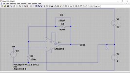
Something like this. The 5 volt rail just gives a negative supply. If the circuit is self contained then this can be derived from a single rail by means of a Zener or LED.
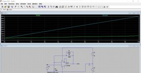
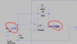
This shows the input and output voltage tracking between 0 and 5 (0 and 50) volts. The DC gain is set by the ratio of the resistors (900k/100k) + 1
High values give lower current consumption but can be any values that give the required ratio.
Final shows shows the accuracy, it is essentially determined just be the tolerance of the two gain setting resistors.
The cap is for stability (to prevent oscillation).


Attachments
Are you sure the digital meter needs 10mA?
What about turning the analogue voltage into a squarewave (NE555) and then using a voltage multiplier (5x, 10x or so).
What about turning the analogue voltage into a squarewave (NE555) and then using a voltage multiplier (5x, 10x or so).
Mmmh, forget about my "idea".
Got carried away and thought you have at least 5V input.
Also the NE555 has a relatively high supply current (higher than 10mA).
Are there any other voltages in the circuit you could use to create the needed power supply for Mooly´s circuit?
Otherwise its probably easier to find another digital meter.
My supply signal is a transconductance 60khz servo motor drive putting out +/-10V (max) with peak 10A
Could a cap/diode values be selected that would see the 60khz as an AC signal for a cap/diode multiplier?
Cockroft-Walton voltage multiplier -- yes -- but you must post-regulate it with a high voltage regulator like the TL783 which is good to 125V to get the 50VCould a cap/diode values be selected that would see the 60khz as an AC signal for a cap/diode multiplier?
I was thinking similar but I'm not sure its viable given the number of stages needed tbh. You are going to need to have a few milliamps available and I just can't see a multiplier doing that really.
The power supply is the stumbling block with this.
The power supply is the stumbling block with this.
- Home
- Amplifiers
- Power Supplies
- DC voltage multiplier for battery powered amp
