Greetings for all,
I’m relative new in the clock design section, so I have my beginner questions. If you feel some inspiration to answer please let me know! Originally I’ve posted this text in another topic, but considering the complexity of the subject I decided to make an own place…
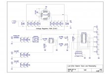
My setup contains the following elements (see photo and schematic):
- DIYinhk USB multichannel XMOS board
- my AK4458 multichannel DAC
- my reclocking board with Crystek CCHD-575 crystal, NB3L553-D buffer and PO74G374A logic gates, supplied from a TPS7A4700 3.3V regulator
The circuit is working good, although it is under testing yet. Before this setup I fed my DAC direct from a MiniDSP USBStreamer, without reclocking the I2S signals. The improvement is obvious: there are more microdetails, finer textures, the instruments are better focused and more separated. Brass instruments and violins are excellent detailed. Overall a more natural presentation, not so fuzzy like a typical "digital" sound.
But! After some experiments I must say that it’s not an easy task to design so a HF circuit correctly. Depending e.g. from the applied bypassing, the sound character changes too! By not adequate setup the higher transients can be too harsh/grainy and the midrange-bass not so articulated, what I'm actually experiencing with my setup. I’d like to make a little technical “walk around” here, to find and understand the optimal environment for such a circuit.
I’ve found some very helpful literature:
- Application Manual for Power Supply Noise Suppression and Decoupling for Digital ICs
https://www.murata.com/~/media/webrenewal/support/library/catalog/products/emc/emifil/c39e.ashx
- Johnson-Graham: High-speed Digital Design (A Handbook of Black Magic)
Please find attached an excel-sheet, adapted from this book. I’ve made it for myself, to understand the basics and to have a good starting point. The applied models are relative simple (capacitors modelled only with capacitance and a serial inductance), but I think it doesn’t harm to make a check like this and make some thoughts…
Another try is to collect as good as possible spice models from the manufacturers (Murata, Kemet, Panasonic etc.) and drop them into a simulator (e.g. TINA). Feel free to experiment with that!
My next step will be to make some jitter measurements with injected noise into the power lines. Will try simply to superpose e.g. 0,1V sinusoidal signal with changing frequency and see what happens on the clock and other outputs… I hope I can determine a reasonable targeted noise floor what a supply line must be achieve to get an appropriate audio playback.
I’ll try to split the psu-lines of the ICs (clock, buffer, gates) and supply them with different voltage regulators. TPS7A4700, LT3042, shunt, LF33CV, etc.
So, I leave rather no questions at the end, because I’ve to experience it myself, but still the message: if you feel to say some advice please make it! 🙂
Thanks for your attention!
I’m relative new in the clock design section, so I have my beginner questions. If you feel some inspiration to answer please let me know! Originally I’ve posted this text in another topic, but considering the complexity of the subject I decided to make an own place…
My setup contains the following elements (see photo and schematic):
- DIYinhk USB multichannel XMOS board
- my AK4458 multichannel DAC
- my reclocking board with Crystek CCHD-575 crystal, NB3L553-D buffer and PO74G374A logic gates, supplied from a TPS7A4700 3.3V regulator
The circuit is working good, although it is under testing yet. Before this setup I fed my DAC direct from a MiniDSP USBStreamer, without reclocking the I2S signals. The improvement is obvious: there are more microdetails, finer textures, the instruments are better focused and more separated. Brass instruments and violins are excellent detailed. Overall a more natural presentation, not so fuzzy like a typical "digital" sound.
But! After some experiments I must say that it’s not an easy task to design so a HF circuit correctly. Depending e.g. from the applied bypassing, the sound character changes too! By not adequate setup the higher transients can be too harsh/grainy and the midrange-bass not so articulated, what I'm actually experiencing with my setup. I’d like to make a little technical “walk around” here, to find and understand the optimal environment for such a circuit.
I’ve found some very helpful literature:
- Application Manual for Power Supply Noise Suppression and Decoupling for Digital ICs
https://www.murata.com/~/media/webrenewal/support/library/catalog/products/emc/emifil/c39e.ashx
- Johnson-Graham: High-speed Digital Design (A Handbook of Black Magic)
Please find attached an excel-sheet, adapted from this book. I’ve made it for myself, to understand the basics and to have a good starting point. The applied models are relative simple (capacitors modelled only with capacitance and a serial inductance), but I think it doesn’t harm to make a check like this and make some thoughts…
Another try is to collect as good as possible spice models from the manufacturers (Murata, Kemet, Panasonic etc.) and drop them into a simulator (e.g. TINA). Feel free to experiment with that!
My next step will be to make some jitter measurements with injected noise into the power lines. Will try simply to superpose e.g. 0,1V sinusoidal signal with changing frequency and see what happens on the clock and other outputs… I hope I can determine a reasonable targeted noise floor what a supply line must be achieve to get an appropriate audio playback.
I’ll try to split the psu-lines of the ICs (clock, buffer, gates) and supply them with different voltage regulators. TPS7A4700, LT3042, shunt, LF33CV, etc.
So, I leave rather no questions at the end, because I’ve to experience it myself, but still the message: if you feel to say some advice please make it! 🙂
Thanks for your attention!
Attachments


Last edited:

I've found in an other forum the following text:
"The 575 makes the LKS sound very harsh and bright which is one of the typical criticisms of the Sabre32, it was one of the first things I removed from the LKS. The 950X makes the presentation more organic and analog like."
"I replaced the CCHD-575 with higher performing CCHD-950X. The 950X gets rid of the treble emphasis without losing the details and resolving capability of the DAC."
“…changing the 575-50 XO will give you much better midrange and take the edge off the high frequency response, less sibilance. The 575 was popular a few years ago but the newer designs have stopped using them.”
So... It seems I have to redesign the whole concept...🙁
An intresting manual: https://www.analog.com/media/en/dsp-documentation/evaluation-kit-manuals/DC2429AF.PDF
Last edited:
I've decided to make a whole new concept, with changeable oscillator. The first challange is to design a proper adapter-pcb. I took some ideas from Ian (Canada), and adapted with my experiences and know-how.
The basic adapter solution has the problem, that the power and ground connections are forming a relatively large (>10nH) loop (because they are in the opposite corner of the 2x7 pin socket), making the PDN impedance worse in the HF region. I've expanded a little the pcb area and added 2 extra GND pins beside the power pin to keep the loop as small as possible.
The basic adapter solution has the problem, that the power and ground connections are forming a relatively large (>10nH) loop (because they are in the opposite corner of the 2x7 pin socket), making the PDN impedance worse in the HF region. I've expanded a little the pcb area and added 2 extra GND pins beside the power pin to keep the loop as small as possible.
Attachments


If you are putting so much effort in decoupling techniques, why aren't you using ferrite beads? They significantly reduce the RF current through the groundplane (and thus common impedance coupling). It also reduces resonances because ferrites are lossy at high frequencies.
Also, it's generally not recommended to put a groundplane under an oscillator. Some oscillators have high impedance amplification stage (like the jfet in a TWTMC version). This allows for easy coupling from and to the groundplane and thus jitter and polution of the ground.
I also recommend checking out PCB Toolkit from Saturn PCB. It's a neat calculator for calculating parasitic inductances and capacitances (and various amounts of other things).
Personally I think a single 0402 capacitor (or reverse topology variant), a ferrite and 3 terminal capacitor (like in the Murata paper you listed) would give a better result. The Murata capacitor can be quite big in value to reduce the effectiveness at low frequencies.
Parralleling capacitors for hf decoupling doesn't work as effectively as a single small capacitor. Mainly because they form a resonant circuit on their own!
A 0805 capacitor has a width of 1.2mm, If you would place them right next to eachother we would have a distance of 2*1.2mm (center of pad to center of pad). This would give a rough inductance of 2nH. The two capacitors form a loop and are effectively in series. This results in a LC circuit with 2nH and 16.5nF -> 27.7MHz.
Though I assume no ESL of the cap here and there is practically more space between the capacitors. The effective resonance frequency will be lower. As you can see it can get really close to the oscilators fundamental.
Thanks for the comments!
So, generally I do not use 0402 components, these are simply too small for hand soldering. I've experimented in the simulator with some 0603 types but I do not feel a need to use them, 0805 are doing the job just fine. The impedance between them are about 0,1nH (do not included the cap inductances itself of course)! How did you calculated the 2nH???
I know the Saturn software, but I must say it is not very usefull for me... I use e.g. this site: https://www.eeweb.com/tools/rectangle-loop-inductance
Ferrite beads are excellent to achive a good noise performance, but they increases drastically the supply line impedance, what I do not want actually. I will supplying all the 3 ICs (osc., buffer, potato) from different voltage regulators, so the suppression of emitted noise is not a task to obtain. Or am I wrong?
The oscillator will be the Crystek CCHD-957, mounted originally an a small pcb, see photo. I do not see a problem with ground planes...
The Murata 3 pin caps (NFM) could be a good option anyway, but I do not have a real experience how they sound...!? Perhaps will make a pattern for that, and if I don't like it simply replace with a short.
If you are putting so much effort in decoupling techniques, why aren't you using ferrite beads? They significantly reduce the RF current through the groundplane (and thus common impedance coupling). It also reduces resonances because ferrites are lossy at high frequencies.
Also, it's generally not recommended to put a groundplane under an oscillator. Some oscillators have high impedance amplification stage (like the jfet in a TWTMC version). This allows for easy coupling from and to the groundplane and thus jitter and polution of the ground.
I also recommend checking out PCB Toolkit from Saturn PCB. It's a neat calculator for calculating parasitic inductances and capacitances (and various amounts of other things).
Personally I think a single 0402 capacitor (or reverse topology variant), a ferrite and 3 terminal capacitor (like in the Murata paper you listed) would give a better result. The Murata capacitor can be quite big in value to reduce the effectiveness at low frequencies.
Parralleling capacitors for hf decoupling doesn't work as effectively as a single small capacitor. Mainly because they form a resonant circuit on their own!
A 0805 capacitor has a width of 1.2mm, If you would place them right next to eachother we would have a distance of 2*1.2mm (center of pad to center of pad). This would give a rough inductance of 2nH. The two capacitors form a loop and are effectively in series. This results in a LC circuit with 2nH and 16.5nF -> 27.7MHz.
Though I assume no ESL of the cap here and there is practically more space between the capacitors. The effective resonance frequency will be lower. As you can see it can get really close to the oscilators fundamental.
Attachments

Last edited:
Thanks for the comments!
So, generally I do not use 0402 components, these are simply too small for hand soldering. I've experimented in the simulator with some 0603 types but I do not feel a need to use them, 0805 are doing the job just fine. The impedance between them are about 0,1nH (do not included the cap inductances itself of course)! How did you calculated the 2nH???
I know the Saturn software, but I must say it is not very usefull for me... I use e.g. this site: https://www.eeweb.com/tools/rectangle-loop-inductance
0402 is doable for me, you need good tools and some practice though. As I said there are also reverse geometry parts which are nice for their low ESL properties. These are easier to solder because they are the size of 1206 I believe (don't quote me on that though).
The way I calculated the trace length is by using the SaturnPCB toolkit. I used a conductor with of 0.7mm. The PCB height is 1.6mm (standard FR-4). This resulted in a inductance of 0.5863nH/mm. The minimum tracelength is 2*1.3mm (center to center, it's the padwidth of a standard 0805 capacitor). 2.6*0.5863 = 1.52438nH. I think I made a mistake somewhere.


I've added an image so you can see what I did.
Ferrite beads are excellent to achive a good noise performance, but they increases drastically the supply line impedance, what I do not want actually. I will supplying all the 3 ICs (osc., buffer, potato) from different voltage regulators, so the suppression of emitted noise is not a task to obtain. Or am I wrong?
Personally I find it much easier to think in currents when looking at decoupling circuits. Decoupling capacitors are there so the loop current is very small. They also function as RF short circuit to ground. A decoupling capacitor however doesn't reduce the current!
Groundplanes are largely inductive. If we then have a high RF current through our groundplane we allow a voltage gradient to occur (= common impedance coupling). We clearly don't want common impedance coupling so we have to reduce the RF current. The only way to do this is to increase the impedance for high frequencies and keep the impedance low for low frequencies! This means we have to use some form of inductor. Ferrites are often used because they become lossy at high frequencies (it's an actual frequency dependant resistor).
Properly simulating ferrite beads is quite tricky and I'm struggling with that part myself. It's mostly hard because their lumped element values change over current and over frequency. If you are interested you might want to check out these articles:
Ferrite Beads Demystified | Analog Devices
https://www.analog.com/media/en/technical-documentation/application-notes/AN-1368.pdf
I think you are confused that ferrite beads increase the COMMON impedance of the supply line. That would be bad practice. However we can use the ferrites in front of every IC to reduce it's RF current. This way there is little common impedance, but still good supply rejection!
Guido Tent of Tentlabs and Grimm Audio has published a document about supply decoupling which I find quite usefull. It's a bit old and thus the exact values can differ a bit, but the main principle is still very valid! You can find the paper here: http://members.chello.nl/~m.heijligers/DAChtml/Supply_decoupling.pdf
The oscillator will be the Crystek CCHD-957, mounted originally an a small pcb, see photo. I do not see a problem with ground planes...
There is not a problem with groundplanes. The problem lies within laying them down under super sensitive circuits that have high impedance.
Here is the original circuit/PCB by Herbert Rutgers (also of Grimm Audio). He was one of the designers of the TWTMC project here on DIYaudio.

It's in dutch but RED = High impedance, Pink = medium to high impedance, Black is low impedance.
The ground plane is an inductor, the traces near the JFET are inductive. Mutual inductance causes the currents to couple. If we allow a small current to be coupled in to an high impedance we get a large voltage! Jfets just so happen to be voltage controlled current sources and the result is a lot more jitter!
The result is that Herbert just cuts open the ground plane. This prevents inductive coupling! The actual PCB design looks like this:

If you REALLY want to be carefull about layout you place it on the edge of your PCB and prevent the formation of a slot antenna. Though I seriously doubt this will have an influence.
I know you aren't using the TWTMC as your main oscillator. However the Crystek CCHD-957 also has a low jitter oscillator circuit in it's enclosure. We don't know how they build it (unless you take it apart). The best we can do is assume a worst case scenario and assume it's high impedance!
The Murata 3 pin caps (NFM) could be a good option anyway, but I do not have a real experience how they sound...!? Perhaps will make a pattern for that, and if I don't like it simply replace with a short.
Things parts that sound the best to me are the parts that are consistent. No weird value changes when DC biased is applied, no weird impedance peaks, linear output impedance (in the sense that it changes very little with current drawn).
Best of luck!

hello,
I'd like to add a 10MHz master clock to a Mutec MC3+.
Prices of finished products are too high.
So, I'm wondering if it is finally easy & "cheap" to build it myself.
Question : is it that simple to build a 10MHz sinewave master clock ?
My idea :
At Digikey, you can have a good OXCO, with good characteristics (stability / phase noise) from 70-80USD
I have good LPS modules that can deliver the right voltage (OXCO working at 3.3V is fine for me)
I put the OCXO on the tiny PCB => 75ohm BNC connector soldiered close to the clock
Power supply next to it
that's it ?
Is it that simple ? or I'm completly wrong ?
Thanks for advice & feedback
Rgds
Question : is it that simple to build a 10MHz sinewave master clock ?
Yes and no. It depends on how good you want the final result to be. If you just want to see something that kinda looks like a 10MHz sinewave a scope, you might not be too far off.
OTOH if you want a low 'close-in' phase noise oscillator suitable as a reference for a high performance audio reproduction system, then its not nearly that simple. Moreover, much of the stuff being tried earlier in the thread turns out to be far from ideal. Too much reliance on textbook high speed digital design when in reality most of what they are dealing with is analog RF. Different enough animal to make a difference in design approach. My two cents, anyway.
Of course, if the goal were to reduce jitter and other processing artifacts to a minimum then I personally would ditch the Mutec and use a different approach altogether.
All the foregoing IMHO, nothing more.
hello Markw4
Thanks for your feedback.
What's your experience in master clock or tweaking clocks ?
you tried yourself and crashed into the "big noise" wall ? 🙂
very hard to get a dead clean signal ?
I wonder if it could work to build a fairly simple 10MHz, because of a few points :
1. in audio, sinewave or squarewave clocks are required. According to some posts & docs, it's easier to build a sinewave MClock, because the the signal is simpler, and with lower phase nosie than squarewave clocks (I read that, but didn't verify myself).
2. we have on the shelf of Digikey / Mouser etc, some OCXO, sinewave, 10MHz, 10ppb max stability, with pretty nice phase noises => from 70USD !
thus, my guess is : that simple !
Of course the PS will have to be dead clean, but I'm used to that.
3. prices of master clocks (finished product) are very high to me. Why paying 1k or 2k USD for finished product, vs the 200-300USD of a DIY stuff ? (70usd for the ocxo + 200USD for the PS)
4. I own a Mutec MC3+, well known to be a pretty good word clock source & distributor of word clock signal.
I use to distribute the word clock signal to my monitors (Dynaudio Core).
The Mutec MC3+ works very well but AFTER replacement of the internal SMPS by LPS (transformer + MPaudio ALD module, LT3045 based).
Thus, the Mutec MC3+ has a pretty nice PCB, but the internal PS really kills it.
So, I don't fancy to pay a lot of money for a brand new master clock if I have to look into it to tweak this & that.
5. I only have a small experience in clock replacements on PCB (did it on USB-to-spdif interface / streamer UPNP / others) ; I replaced basic quartz or XO by ConWin OCXO, and each time it was night-day. So, why not this time ?
If my plan is to get a DIY master clock, it will be to beat the 1GHz (and its PLLs) of the Mutec <= of course, it looks like another challenge than beating XO or quartz, doesn't it ? 🙂 but is it the really hard stuff we expect ?
I stop there my brainstoming 🙂
Feel free to comment if you have experience in that.
Rgds
PS : I'm pretty sure I missed something, but I don't see it yet... 🙄
Thanks for your feedback.
What's your experience in master clock or tweaking clocks ?
you tried yourself and crashed into the "big noise" wall ? 🙂
very hard to get a dead clean signal ?
I wonder if it could work to build a fairly simple 10MHz, because of a few points :
1. in audio, sinewave or squarewave clocks are required. According to some posts & docs, it's easier to build a sinewave MClock, because the the signal is simpler, and with lower phase nosie than squarewave clocks (I read that, but didn't verify myself).
2. we have on the shelf of Digikey / Mouser etc, some OCXO, sinewave, 10MHz, 10ppb max stability, with pretty nice phase noises => from 70USD !
thus, my guess is : that simple !
- you pay 70USD for this sugar piece
- put it on tiny PCB
- connect a BNC 75ohm connector between the GND & signal pins of the OXCO
- power the OCXO by connecting its Vcc & GND pins to a nice PS
Of course the PS will have to be dead clean, but I'm used to that.
3. prices of master clocks (finished product) are very high to me. Why paying 1k or 2k USD for finished product, vs the 200-300USD of a DIY stuff ? (70usd for the ocxo + 200USD for the PS)
4. I own a Mutec MC3+, well known to be a pretty good word clock source & distributor of word clock signal.
I use to distribute the word clock signal to my monitors (Dynaudio Core).
The Mutec MC3+ works very well but AFTER replacement of the internal SMPS by LPS (transformer + MPaudio ALD module, LT3045 based).
Thus, the Mutec MC3+ has a pretty nice PCB, but the internal PS really kills it.
So, I don't fancy to pay a lot of money for a brand new master clock if I have to look into it to tweak this & that.
5. I only have a small experience in clock replacements on PCB (did it on USB-to-spdif interface / streamer UPNP / others) ; I replaced basic quartz or XO by ConWin OCXO, and each time it was night-day. So, why not this time ?
If my plan is to get a DIY master clock, it will be to beat the 1GHz (and its PLLs) of the Mutec <= of course, it looks like another challenge than beating XO or quartz, doesn't it ? 🙂 but is it the really hard stuff we expect ?
I stop there my brainstoming 🙂
Feel free to comment if you have experience in that.
Rgds
PS : I'm pretty sure I missed something, but I don't see it yet... 🙄
I have done a lot of experimentation with dac clocks, clock distribution, and reclocking. I would like to talk about the results to date in more detail here in the forum someday, but have agreed to wait on that.
At this point I can tell you some general things I have already talked about here and there in the forum. Pretty much its like this: (1) everything matters, every little detail, and (2) nobody here in the forum has publicly shown they know how to do it really well.
Also, presumebly the Mutec already has some kind of reference clock inside since it is basically a frequency synthesizer at its core. It will have more jitter than a good crystal no matter what simply because of how a synthesizer works. A better reference clock may improve on the likely-cheap clock they use by default, but a poor external clock implementation may make the device perform worse than it does now.
That said, no reason why you can't have some fun experimenting 🙂
Hi Markw4,
nice summary 👍
Right now, I step back because of the "load" impedance ?
I confess I don't understand the issue regarding impedance of the load in that kind of stuff.
The Mutec is an audio device, and the master clock plug is 75ohm
The OCXO on the market are 50ohm.
On eevblog a guy posted DSO screenshots to show that on a squarewave signal => if you measure the signal of a 50ohm clock going thru a 75ohm cable => the squarewave is not square any more 👎
Is it an issue on a sinewave ?... I guess yes, too.
Mutec states that you can use a gps clock as master clock... but gpsclocks have 50ohm outputs, not the 75ohm required by the interface. Strange.
I'll ask Mutec by mail to get a clear feedback about that.
Rgds
Look up 'characteristic impedance,' perhaps like so: https://www.google.com/search?q=wha...512l6j0i390.9455j1j1&sourceid=chrome&ie=UTF-8
Then look up 'transmission line termination,' again, maybe something like this: https://www.google.com/search?q=wha...BkQGIAZkHkgEDMS43mAEAoAEBwAEB&sclient=gws-wiz
Also, with sine waves we sometimes use a concept termed 'VSWR,' which might be specified in some way on a sine wave oscillator datasheet: https://www.google.com/search?q=wha...i57j0i390l3.5592j0j1&sourceid=chrome&ie=UTF-8
Then look up 'transmission line termination,' again, maybe something like this: https://www.google.com/search?q=what+is+transmission+line+termination&rlz=1C1CHBF_enUS771US771&sxsrf=APq-WBuLDsxoJ-PAPPyT6IPyerEafjfmNg:1650716501011&ei=Ve9jYp0v6pPQ8Q-Hk7S4CA&ved=0ahUKEwjdrauVlqr3AhXqCTQIHYcJDYcQ4dUDCA4&uact=5&oq=what+is+transmission+line+termination&gs_lcp=Cgdnd3Mtd2l6EAMyBggAEAgQHjIFCAAQhgMyBQgAEIYDOgcIIxCwAhAnOgQIABANOgoIABAIEAcQChAeOgYIABANEB46CAgAEA0QBRAeOggIABAIEA0QHjoICAAQCBAHEB5KBAhBGABKBAhGGABQAFiXB2CpCWgAcAF4AIABkQGIAZkHkgEDMS43mAEAoAEBwAEB&sclient=gws-wiz
IMHO, the PCB traces will have some pitfalls as hardly to made on PCB 50E transmission lines...
AKM likes to have monotonic square wave forms, so overshoots the check using nice DSO & probe, as xxk$ gear
@Markw4
I've read some stuff regarding the impedance matching 50 / 75ohm.
Apparently,
on a squarewave we have big distortion when the signal goes thru 50 to 75 ohm mismatch
but I found no feedback regarding sinewave ; I guess we have distortion, but sinewave is quite different than squarewave obviously : no fast transient. So I guess the distortion is less an issue with sinewave.
Anyway, in that stuff, the key point is jitter. We can have small distortion when passing from 50 to 75ohm, the jitter may not be affected (jitter = jitter of the TCXO or ocxo)), because we have a passive "process" here.
Just a guess of course...
@HpW :
what do you mean by "the PCB traces will have some pitfalls as hardly to made on PCB 50E transmission lines..." ?
I don't know AKM chip precisely...
Why do they prefer squarewave ? Is it like to hardware ? if yes, how can it be ?
I'll do some measurements with my DSO (Siglent SDS2104x+, a nice one, but far less than xxkUSD ! 🙂 ). What's yours ?
Delivery from Digikey should arrive today, I'll have a try this weekend.
I bought a tcxo at 11EUR & an ocxo Conwin at 70EUR, to see if the ocxo really worth it regarding SQ. I don't have any idea about the results 🙂
Rgds
Power is still reflected back into the output of a sine wave clock if there is a mismatch. Might not be good for oscillatory stability. In the worse case it could damage the oscillator output stage.
The nice thing about a square wave is that if you careful making it and not distorting it, then it is less likely for amplitude noise to be turned into phase noise at the receiving end (inside the Mutec) where the since wave will probably be squared in order for it to work with Mutec digital logic.
The nice thing about a square wave is that if you careful making it and not distorting it, then it is less likely for amplitude noise to be turned into phase noise at the receiving end (inside the Mutec) where the since wave will probably be squared in order for it to work with Mutec digital logic.
- Home
- Source & Line
- Digital Line Level
- Design steps of building a low-jitter master clock