I built this amp a few years ago out of a rca199 portable record player. I used whatever I had on hand from salvaging parts and it turned out pretty good. It had a 5y3:rectifier tube that went to 47uf cap>56ohm resistor>20uf film cap>820 resistor>47uf cap. I used the 56ohm resistor in place of the Hammond choke. The wire was run point to point and I used a rudimentary bus type grounding scheme that went zig zag instead of straight through the stages. It was also tied to the chassis on both ends. The bad part is I used a 2 prong cord with no ground. But! Without ever checking a single voltage or bias current the amp played awesome for a few years through some pioneer bookshelf speakers.
Im currently disassembling it in order to rebuild it the right way on a 12x8 Hammond chassis. I'm going to use new parts better resistors and I'm stuck on the output transformers. The ones I used from the original circuit worked with 8 ohm speakers and they are twice the size of the pt31's I ordered.
Question is. How do I check the impedance of it.
I have a lcr meter that can check dcr and inductance at various frequency's. Would this somehow work?
I have many questions....
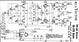
Here is the original circuit. Note how they used a tap on the output transformer +
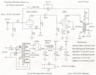
This is current state of affairs besides the power supply differences and unknown output transformer.
I found this (a lot of searching)and it almost matches the part number on my transformer 962228-2
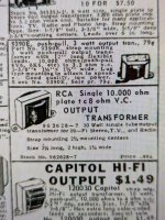
Here's the original trafos compared to the p-t31
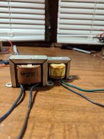
And this is what I built and I'm about to dismantle.
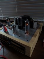
using salvaged parts.
I'm hoping some experts might read this. I'd like to add a headphone jack this time around to power some 80ohm headphones for my father. (Focal utopia)
Btw the amp only hummed when unconnected and when avery high end DAP was paused or between song. (Weird)
Im currently disassembling it in order to rebuild it the right way on a 12x8 Hammond chassis. I'm going to use new parts better resistors and I'm stuck on the output transformers. The ones I used from the original circuit worked with 8 ohm speakers and they are twice the size of the pt31's I ordered.
Question is. How do I check the impedance of it.
I have a lcr meter that can check dcr and inductance at various frequency's. Would this somehow work?
I have many questions....
Here is the original circuit. Note how they used a tap on the output transformer +

This is current state of affairs besides the power supply differences and unknown output transformer.

I found this (a lot of searching)and it almost matches the part number on my transformer 962228-2

Here's the original trafos compared to the p-t31

And this is what I built and I'm about to dismantle.

using salvaged parts.
I'm hoping some experts might read this. I'd like to add a headphone jack this time around to power some 80ohm headphones for my father. (Focal utopia)
Btw the amp only hummed when unconnected and when avery high end DAP was paused or between song. (Weird)
Last edited:
. The ones I used from the original circuit worked with 8 ohm speakers and they are twice the size of the pt31's I ordered.
Question is. How do I check the impedance of it.
Which transformer do you want to check...? Which impedance? Primary, secondary? Not quite following you on your transformer switchout. The originals are better.
The original RCA output transformer doesn't have it's resistance or impedance anywhere. I want to see if they will work or will I get better results with the transformers the circuit is designed around.Which transformer do you want to check...? Which impedance? Primary, secondary? Not quite following you on your transformer switchout. The originals are better.
Primary and secondary
The original RCA output transformer doesn't have it's resistance or impedance anywhere. I want to see if they will work or will I get better results with the transformers the circuit is designed around.
Primary and secondary
The RCA tranny was made for the 6BQ5 so you can assume the primary side will be 100% good for the DG circuit. The voltages are within any normal design for the 6BQ5 so the primary isn't an issue. The main difference is in the secondary side with the addition of the FB line taken from an 8 ohm tap. If you don't have the rating of the speakers in the RCA, then to calculate it you have to get the turns ratio of the tranny and use an educated guess on the primary Z, which would be about 6K for an SE 6BQ5 circuit. Then with those two numbers you can calculate the approximate secondary tap rating. If it comes out to something other than @8 ohms you would adjust the FB resistor, and use other speakers. If you use 8 ohm speakers, the reflected impedance will be close enough to use the circuit as is. Have fun.
Yes. RCA was so proud of that trick that they took out a US patent. (IIRC, Philips invented and patented it in Europe too.)Note how they used a tap on the output transformer +
It gives a reduction of hum/buzz a few pennies cheaper than just doing good filtering. You are not counting your last penny like a factory has to. Your second plan has great filtering. That or a little less (C-R-C) will do nicely.
V/I of that 6BQ5/EL84 is 5,800 Ohms. You low-load a pentode, so 5k is THE happy load here. This is also the most common for a small SE OT.