I have 2 power amps that I would like to bi-amp in my system. They have different gains.
So I took some measurements with my scope, and here is what I measured. Both amp inputs were fed with a 1 kHz sine wave, with an 8ohm dummy load across the speaker terminal.
Amp A:
Input impedence: 15kOhms
Input voltage: 330mV
Output voltage: 4.5v
Amp B:
Input impedence: 100kOhms
Input voltage: 330mV
Output voltage: 7.2v
If I use the following formula to calculate db,
Lv = 20 log10 V0/V1 db (see attached for better rendering)
Amp A:
Gain: 22.7db
Amp B:
Gain: 26.7db
So, does this mean I need to drop 4db to get the output level from both amps to be closer together?
Does the input impedence for each amp make any difference?
The output impedence of my preamp is 600ohm.
If so, would a 3db attenuator, like the Harrison product in the attachment be close enough?
I also watched a YouTube video from PSAudio, saying a voltage divider would work. I'm making assumptions that the attenuator is just that in a consumer friendly package.
Any help would be appreciated. Thanks.
Josh
Attachments

You either have to drop the gain of one or increase the gain of the other. Dropping with an attenuator is easiest... and that attenuator could be a preset pot so you can get the levels spot on.
Input impedance matters only in absolute terms. If both amps are connected to the 600 ohm source then the level has already been reduced. In practical terms the attenuator setting will slightly alter things.
This is something you could sit down and try and calculate... but are those impedances accurate in the first place.
I would just add a preset volume control of say 20k and set the levels to be identical. You could then carefully remove the preset and measure the exact resistors needed to make it permanent.
Why are you even going to dB??
Input voltage: 330mV, Output voltage: 4.5v, gain= 4.5/0.33 or 13.6
Input voltage: 330mV, Output voltage: 7.2v, gain= 7.2/0.33 or 21.8
You want to reduce gain of 21.8 to gain of 13.6. So you want 1.6:1 of loss. Thinking lazy, this could be 600r+1000r L-pad.
Input voltage: 330mV, Output voltage: 4.5v, gain= 4.5/0.33 or 13.6
Input voltage: 330mV, Output voltage: 7.2v, gain= 7.2/0.33 or 21.8
You want to reduce gain of 21.8 to gain of 13.6. So you want 1.6:1 of loss. Thinking lazy, this could be 600r+1000r L-pad.

Remember:
Preamp is feeding both amps - so the input impedances are in parallel.
Attenuator impedance will be in parallel with that amp's input impedance.
You want total input impedance as seen by pre to be above at least 10k.
A pot is the easiest/most convenient way.
Preamp is feeding both amps - so the input impedances are in parallel.
Attenuator impedance will be in parallel with that amp's input impedance.
You want total input impedance as seen by pre to be above at least 10k.
A pot is the easiest/most convenient way.
@PRR
I was going to db, since that was the units of the attenuator.
@jakruby, thanks. I will keep the parallel impedence in mind.
@mooly
The impedence is from manufacturer specs.so who knows.
I think I will use a pot. to see what R values get the levels equal. Seems like a great opportunity to get better at usit my 2channel scope. 🙂
Thanks for the help everyone.
In case you are curious, the preamp is the the pre section of Marantz PM8005. Power amps are the power section of Marantz, and a Bob Carver Crimson 275.
The Carver has the higher gain. I just thought of another option, I could also sub the stock output tubes in the carver too. Hmmm...
In case you are curious, the preamp is the the pre section of Marantz PM8005. Power amps are the power section of Marantz, and a Bob Carver Crimson 275.
The Carver has the higher gain. I just thought of another option, I could also sub the stock output tubes in the carver too. Hmmm...
Last edited:
@mooly
The impedence is from manufacturer specs.so who knows.
I think I will use a pot. to see what R values get the levels equal. Seems like a great opportunity to get better at usit my 2channel scope. 🙂
Absolutely 🙂 A pot is definitely the way to go but do remember that you can use a preset pot as well and you can also fit fixed resistors in place of the pot once you know the values (by measuring the pot).
Absolutely 🙂 A pot is definitely the way to go but do remember that you can use a preset pot as well and you can also fit fixed resistors in place of the pot once you know the values (by measuring the pot).
I pick up what you are saying. The pot is just a measurement tool or proxy for the final resistors I will need to source.
Yes, and there are two ways of setting the pot up.
1/ As a conventional control with the output taken from the wiper. You would need to measure both 'legs' of the divider chain to derive the two fixed values needed, that is to say from wiper to each end lead.
2/ You could use a fixed value resistor (say 10k) and have the preset/pot form the adjustable lower half of the chain only. That is a good option and means only one resistor has to be measured and fitted.
I finally got around to hooking this pot via Mooly's suggestion #2. I used a 10k volume potentiometer.
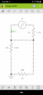
with a 1.77k inline on the signal input to the amp, and the pot between signal (after the 1.77k R) and ground, I measured 4.12k Ohms.
Do the values of these resisters matter much? Or only the ratio between them? The input impedence of the amp is 100k, should I try and get my resister values higher or lower?
After thinking about this a bit more, I think I may have hooked up my test circuit with a missing connection between on the - side of the RCA cable.
So I think I will retest again tomorrow.
I did think to measure resistance with my multimeter. It reads only ~4kOhm across V1(see schematic), which would be the preamp side of the setup.
Probably I want to adjust my resister values to be higher, so it reads above 10k?
So I think I will retest again tomorrow.
I did think to measure resistance with my multimeter. It reads only ~4kOhm across V1(see schematic), which would be the preamp side of the setup.
Probably I want to adjust my resister values to be higher, so it reads above 10k?
Attachments
Yes, I think you have drawn the circuit incorrectly 🙂 The attenuation of 1.77 and 4.12k is not very much. The 100k input impedance is high enough not to significantly effect anything.
The values are OK for most solid state gear which should easily drive those values. It is the ratio that sets the attenuation but in practice you should not go to high either as that can cause other problems. 10 to 20k is a usually a good value to aim for.
You can just use the preset alone with no other resistor. Connect the 10k preset across the audio output (the source) using the end legs of the preset and then take the signal from the middle wiper leg of the preset.
Attachments

7.2/4.5=1.6X attenuation needed
Which means: 4.08dB=4dB (in the Real World)
From: dB calculate - decibel calculation dB calculator voltage power ratio sound pressure level matching dBA SPL sound pressure intensity ratios converter thd percent % audio engineering impedance matching bridging - sengpielaudio Sengpiel Berlin whih I recommend, tons of excellent Audio calcuators there, very useful.
Designing around what you have, attenuate Amp B whih to boot has higher impedance, making things easier.
My choice (there are others possible of course):
* Add 100k in parallel with amp B input, so combination is 50k.
* add 0.6*50k resistor in series, so 30k (in practice 33k is close enough)
Presto!!!!
PD: for the ultimate confirmation and peace of mind, join both amp inputs togeter, feed them 330mV and confirm both output 4.5V
Easy peasy.
No need for OCD , within 10% of each other is enough, worst case slightly adjust the "30k" resistor.
Last edited:
30k:50k divider could be a bit noisy by producing a high impedance node sensitive to pickup (if not screened) and by adding some Johnson noise (probably not an issue at line level). However it is the most compatible with a range of sources.
Ok, I hooked everything up again, here are the details. Hopefully, I figured out the correct way. Who would of thought 3 wires would cause me so much trouble.😀 I took the measurements with the preamp at 3 o clock volume. There is also a Scot of the scope with no pot in series, just a wire. And an after adjustment shot.
Amp A = scope channel 1;
Amp B = scope channel 2
In lookin at the pot's schematic (attached).
I measure 8.42k Ohm across the audio output I2 and I3.
I measure 1.75k Ohm across I2 and I1.
I measure 10k Ohm across I1 and I3.
I have the audio source output + fed into I2.
I have the audio source output - fed into I1.
I have the downstream amplifier input signal(+) connected to I3.
I have the downstream amplifier input signal (-) connected to the audio source -.
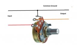
See attached photo.
left black alligator is "audio source output + fed into I2.".
green alligator is "audio source output - fed into I1."
right black alligator goes to amp B's input jack.
I also made a video to help explain how I set this up. Mostly, I just want to make sure I understand what is going on so I can gain a bit of knowledge too.
@Mooly that simulated circuit is cool.
Amp A = scope channel 1;
Amp B = scope channel 2
In lookin at the pot's schematic (attached).
I measure 8.42k Ohm across the audio output I2 and I3.
I measure 1.75k Ohm across I2 and I1.
I measure 10k Ohm across I1 and I3.
I have the audio source output + fed into I2.
I have the audio source output - fed into I1.
I have the downstream amplifier input signal(+) connected to I3.
I have the downstream amplifier input signal (-) connected to the audio source -.
See attached photo.
left black alligator is "audio source output + fed into I2.".
green alligator is "audio source output - fed into I1."
right black alligator goes to amp B's input jack.
I also made a video to help explain how I set this up. Mostly, I just want to make sure I understand what is going on so I can gain a bit of knowledge too.
@Mooly that simulated circuit is cool.
Attachments


Last edited:
Difficult to follow all that 🙂
Like this, two versions, the first allows control over 0 to 100% of the signal level, the second always has some attenuation present depending on the value of the pot.
For example if the pot and resistor are 10k then in the second example you can only ever get a maximum level of 50% of the input.
Both allow the signal to go to zero. The first is the more common arrangement.
Attachments

@Mooly, thanks for the drawings, I understand a lot better now.
The pot I was using was really touchy, but I could get the signals at the speakers close. Then I grabbed a bunch of close resistors from the parts bin and hooked them up to my cheater cable in place of the potentiometer.
The signals are the closest with the following resistors in place. 8k2 across the input side of the amplifier and 3k6 inline with the signal.
I tested the circuit via the schematic that is attached. I also spent some time figuring out ltspice. (Although, I haven't figured out how to rotate a component yet 😛)
I really do appreciate all the help.
I plan on sacrificing a cheap rca cable and testing the values with some music and see how the levels sound before I commit to making a more presentable box/build out.
Attachments

Last edited:
For my own sanity, hooked up via Mooly's 1st drawing, the following readings were taken from the pot, and the levels on the scope equalized.
Input to wiper 3.37kOhm;
Wiper to ground 7.18kOhm;
Input to wiper 3.37kOhm;
Wiper to ground 7.18kOhm;
That's it 
You can rotate a part before placing it using the fourth symbol from the right on the toolbar (greyed out now but won't be when you pick a part).
To rotate the already placed resistor use the scissors to snip the leads so it is free. Right click to deselect scissors. Now use 'drag' (the small hand, left click it). Go over the resistor. Left click and drag it to the rotate symbol and left click. Drag it back to where you want and place it.
- Home
- Source & Line
- Analog Line Level
- Did I calculate my db gain correctly?