Any thoughts,
On using a couple of 1N5818 schottky diodes in series to give a 1 volt cathode bias?
Data sheet.
http://www.vishay.com/docs/93256/1n5818.pdf
Regards
M. Gregg
On using a couple of 1N5818 schottky diodes in series to give a 1 volt cathode bias?
Data sheet.
http://www.vishay.com/docs/93256/1n5818.pdf
Regards
M. Gregg
Are you looking for good voltage regulation against change in operating current and temperature? If so, then what current span is expected?
Are you looking for good voltage regulation against change in operating current and temperature? If so, then what current span is expected?
I know what your going to say the resistor is better..🙂
The only other thing is a MU stage. I just wondered what the thoughts were on using diodes as opposed to LED's.
Regards
M. Gregg
Last edited:
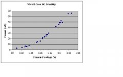
I use them all the time. I prefer the 1A, 600V Cree SiC Schottky diodes, which have Vf ~.85-0.9V in typical tube applications. I used 4 of them in series to bias the 6E5P input tube in my 833C amps to 26mA with 190V on the plate. I also used them in a preamp to bias a 2C22 to 15mA. They have a very low dynamic resistance, especially as you get up above 20mA or so.
Below is a plot that I made from bench measurements of their forward voltage vs current at low current levels. Higher current plots are available on the Cree data sheets.
IMO they sound great! Solid, deep bass response and nice clarity, and of course no bypass cap needed. No LED glow, either.
Below is a plot that I made from bench measurements of their forward voltage vs current at low current levels. Higher current plots are available on the Cree data sheets.
IMO they sound great! Solid, deep bass response and nice clarity, and of course no bypass cap needed. No LED glow, either.
Attachments
I'm exploring bias through semi's and have used these small SMD LED's, I don't know the brand or model number. They drop 1,7V - 1,8V with currents from 3 to 10mA. Is the proper way to establish the impedance like this: 0.1V / 0.007A = 14.2 ohm ?
I'm using these LEDs in a common cathode stage and in a cathode follower. They are in the mid of their operational range (circa 6mA). Biassing both stages through LEDs was not pleasant as bass notes sounded artificial and louder than they actually are. I must confess the power supply is rather high impedance... perhaps this fact plays a role.
Next I tried one stage (V2 in the picture) and indeed bass reproduction seemed deeper but mids and highs were also affected, in an unpleasant way. Now I made a compromise with a resistor / semi combination and it seems to be best of both worlds. The bias resister for the stage would have been circa 2K5. One LED has 1.7V/0.006A= 283 ohm resistance so the advance is 2500-1049= 1451 ohm less resistance in the cathode circuit.
An externally hosted image should be here but it was not working when we last tested it.
Last edited:
Disco, The dynamic impedance can be ascertained from a graph like I posted above or from measurements like yours, it's simply (delta V/delta I). For the Cree diodes I show, between 30mA and 40mA, it would be:
(.892-.878)/(.040-.030) = 1.4 ohm, which is very low. It will be a little higher at lower currents.
For the range of 3-10mA, the dynamic impedance for the Crees would be
(.84-.81)/(.010-.003) = 4.3 ohm
Lower is better. So to get your 1.7V using the Crees you could use two in series for a total dynamic impedance of 8.6 ohm, which is 40% lower than your SMD LEDs.
IMO they sound great! Solid, deep bass response and nice clarity, and of course no bypass cap needed. No LED glow, either.
Thank's for the information,
I have tried a couple of diodes the current was quite low but...after trying a couple of different types I can confirm your findings about the bass.
I even tried a 1n4007 for a laugh and 😡 its sounds good 😀.
Now I remember the LEDS had to be carrying about 5 mA or you got a bright edge on the sound ( so the use of the feeder resistor). The diodes just sound good, so I guess there is no current knee to worry about.
(Can you expand on this?)
1N4007:
http://www.vishay.com/docs/88503/1n4001.pdf
Regards
M. Gregg
Last edited:
Well, I just exchanged the SMD LEDs for a string of 1n914 'Small Signal Fast Switching Diodes' (0.7V each) and the first impression is more presence. Bass was already deep and tight. A change for the better! The 200 ohm is still in use.
Hmmm..... 🙄 I've got some 30BQ060TR SMC schottkies. Next! 😛
Hmmm..... 🙄 I've got some 30BQ060TR SMC schottkies. Next! 😛
Well, I just exchanged the SMD LEDs for a string of 1n914 'Small Signal Fast Switching Diodes' (0.7V each) and the first impression is more presence. Bass was already deep and tight. A change for the better! The 200 ohm is still in use.
Hmmm..... 🙄 I've got some 30BQ060TR SMC schottkies. Next! 😛
Cool.
Those Si schottkys have a pretty low Vf, that's why I prefer the SiC versions with their higher Vf - you can use fewer of them to get the same bias voltage, giving a lower dynamic impedance.
I like infra-red (IR) LED diodes for biasing driver tubes... have you tried them yet? No worry about lighting up the neighborhood with LEDs.
Cheers,
Bob
Cheers,
Bob
I like infra-red (IR) LED diodes for biasing driver tubes... have you tried them yet? No worry about lighting up the neighborhood with LEDs.
Cheers,
Bob
I have some but I never used them once I tried the SiC Schottkys. Maybe some day.
I'm trying to understand the use of semiconducters in the cathode circuit. Is the following true?
If the RMS value of the audio signal is larger than Vf and opposite to the bias voltage, the diodes switch off one at a time. This situation will occur every time a diode sees a higher cathode voltage than anode voltage.
In this graphic:
is the blue line representing the bias voltage,
is the red curve representing a sinus wave or the audio signal.
is the blue line representing the bias voltage,
is the red curve representing a sinus wave or the audio signal.
An externally hosted image should be here but it was not working when we last tested it.
If the RMS value of the audio signal is larger than Vf and opposite to the bias voltage, the diodes switch off one at a time. This situation will occur every time a diode sees a higher cathode voltage than anode voltage.
Your drawing is misleading,
If you look at the symbols and remember that the cathode emits electrons which way are the diodes conducting..😀
However you have to remember the AC is in fact a change in conduction nothing is switching off or on its in conduction all the time. Just the amount of conduction changes with the control on the grid.
Regards
M. Gregg
Here's a better representation:
An externally hosted image should be here but it was not working when we last tested it.
An externally hosted image should be here but it was not working when we last tested it.
Last edited:
Your diagram is correct the diodes point to the ground rail,
But look up conventional and non conventional current flow..
The diodes are shown correctly..
Forget the AC signal for a moment and think that the tube just conducts more or less as the signal on the grid changes..
So the diodes only see a changing conduction.. the sine wave you are referring to is "created" as a result of the change which appears across the anode resistor.
Regards
M. Gregg
Last edited:
That cannot happen. The valve cannot drive its cathode more negative than zero volts; it can only go to zero current (cut-off), which means everything switches off.I'm trying to understand the use of semiconducters in the cathode circuit. Is the following true?
If the RMS value of the audio signal is larger than Vf and opposite to the bias voltage, the diodes switch off one at a time.
- Home
- Amplifiers
- Tubes / Valves
- Diode cathode bias?