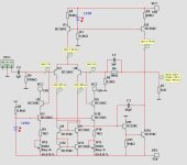
This isn't normally done with a power amp as its complex, adds extra input noise, and output offsets of a few 10's of mV aren't usually an issue. A DC-servo can solve the problem better.
For an opamp it is done in many integrated opamps, but again it increases noise (even if noise-cancelling techniques are used, it relies on both inputs seeing the exact same impedance, which is never the case when low noise is important as in a mic- or phono- preamp.
You get the benefit of being able to use larger value DC-bias resistors in the external circuit (which might otherwise load the circuit or impose DC offsets). Its good for DC precision applications especially, not so much for audio.
In real circuits devices are imperfect and all slightly different, so the precise cancellations that the simulator sees between devices isn't going to happen, you won't see 0.000062% THD in that circuit if built, or anything like that. The way to very low distortion is very high open-loop gain and integrated matched devices.
Well matched NPN and PNP can achieve that with fully symmetrical topology. Like this.

Anyway, the input bias current is not the biggest concern for me with bjt input stage.
The real concern is the low input impedance. The input impedance with bjt is only about Beta times re (if the emitter is not degenerated). re is about 25 Ohm with 1ma bias.
Anyway, the input bias current is not the biggest concern for me with bjt input stage.
The real concern is the low input impedance. The input impedance with bjt is only about Beta times re (if the emitter is not degenerated). re is about 25 Ohm with 1ma bias.
The only way to get build-to-build consistency with this kind of design is to use IC-like techniques. As in, matched devices. You are forced to use two trimpots to get there because none of your devices are matched. Ib's for the LTP pair can differ, so can U5/U6. Then there are the tolerances of the passives to deal with.....
The other issue is that your bias compensation produces fixed current while the devices in the LTP will draw varying amounts of base current, depending on the input offset. But this issue will be minor if the LTP is inside a high-gain NFB loop.
The topology shown in post #3 will do a better job of tracking the bias currents. I have seen other approaches which achieve much the same thing.....but they also rely heavily on well matched devices to work.
A JFET LTP will get you pretty darned close w/o all that extra circuitry.
