Well I have had some time on my hands again, and as the saying goes "Idle hands almost always lead to bizarre things happening".
At least that is the case at my place.
Last time I got this bored, I ended up building a power amplifier entirely from small signal transistors, using 100 devices in the output stage.
This time my idle hands turned their attention to the discrete operational amplifiers that lay unused on my desk (yes, I don't even use the things...). The challenge was "Can I make these using through hole components, but still fit generally onto a DIP8"?
The answer is below...
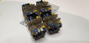
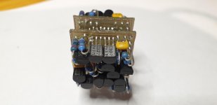
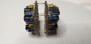
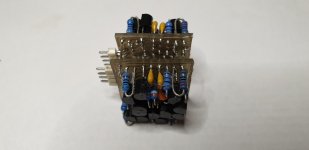
To add to the challenge, as I firmly believe that simulating or "CAD" designing things is a cop out, i set about making them. By doing the PCB's in my shed.
The design is pretty straight forward - I am an engineer, and not such a believer in esoterica - there is little need to go off the planet if making a BJT DOA...
View attachment Schematic Sht1.pdf
View attachment Schematic Sht2.pdf
This would not normally be such a big deal - but these things use 50 thou pads, and include "normal" 0.25w resistors and TO92 transistors. Getting the top and bottom layers of the PCBs to line up was fiddly - and in a couple of areas the bottom layer hole alignment to the top is a touch off.
But they worked.
A PCB from a fab would make assembly really (really) simple. Doing it soldering top and bottom was a hassle!
They work a treat - I haven't measured their performance yet, but considering that they are with the exception of device packaging utterly identical to these:
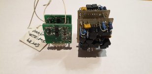
I am assuming they work pretty well the same...
In the end I reckon they look pretty cool. I guess that shows how sad an individual I become when bored. Or how evil my idle hands can become!
If you want to make something like this, I would very (very) strongly recommend using a PCB fro a fab with plated through holes and soldermask!
I have the files if you really want to go old school. Else if you like some microscope work, I have a bunch of PCB's for the surface mount work that I will happily share a few of with anyone needing distraction as much as I do!
At least that is the case at my place.
Last time I got this bored, I ended up building a power amplifier entirely from small signal transistors, using 100 devices in the output stage.
This time my idle hands turned their attention to the discrete operational amplifiers that lay unused on my desk (yes, I don't even use the things...). The challenge was "Can I make these using through hole components, but still fit generally onto a DIP8"?
The answer is below...


To add to the challenge, as I firmly believe that simulating or "CAD" designing things is a cop out, i set about making them. By doing the PCB's in my shed.
The design is pretty straight forward - I am an engineer, and not such a believer in esoterica - there is little need to go off the planet if making a BJT DOA...
View attachment Schematic Sht1.pdf
View attachment Schematic Sht2.pdf
This would not normally be such a big deal - but these things use 50 thou pads, and include "normal" 0.25w resistors and TO92 transistors. Getting the top and bottom layers of the PCBs to line up was fiddly - and in a couple of areas the bottom layer hole alignment to the top is a touch off.
But they worked.
A PCB from a fab would make assembly really (really) simple. Doing it soldering top and bottom was a hassle!
They work a treat - I haven't measured their performance yet, but considering that they are with the exception of device packaging utterly identical to these:

I am assuming they work pretty well the same...
In the end I reckon they look pretty cool. I guess that shows how sad an individual I become when bored. Or how evil my idle hands can become!
If you want to make something like this, I would very (very) strongly recommend using a PCB fro a fab with plated through holes and soldermask!
I have the files if you really want to go old school. Else if you like some microscope work, I have a bunch of PCB's for the surface mount work that I will happily share a few of with anyone needing distraction as much as I do!
Can it fit onto a DIP8 footprint (10x10mm) ?
That is the real challenge.
https://www.diyaudio.com/forums/analog-line-level/218373-discrete-opamp-design-67.html#post5711190
(post #3333)
🙂
Patrick
That is the real challenge.
https://www.diyaudio.com/forums/analog-line-level/218373-discrete-opamp-design-67.html#post5711190
(post #3333)
🙂
Patrick
In low distortion I/V thread @smms73 proposed using double transistors bcm857 / 847 In sot457 package - you can get perfect matching and free space
Unity gain bandwidth approx 6 MHz
Slew rate approx 6 volts/microsecond
Max output current approx 12 mA (Q30)
Slew rate approx 6 volts/microsecond
Max output current approx 12 mA (Q30)
Last edited:
This is the discrete version of a SMD dual op amp. The SMD version does indeed use BCM 847 in the diff pair, and IMT1 in the current mirror.
I did this thru hole version as there are people who are intimidated by SMD work. This is a lot bigger than the SMD version.
Both this and the SMD version are the same electrically (with the exception of the single transistors rather than duals for the diff amp and current mirror). This design includes a lot more than the design here:
Discrete Opamp Open Design
(post #3333)
Not the least the inclusion of current mirrors, VAS buffer and also a high current output stage. Without going to tiny resistors there is no way on earth this would fit in 10 by 10mm - but that was never a goal I has so hey... who cares.
The SMD version is about 17 by 17mm.
Regards
Phil
EVUL, this is the original glog entry, followed by a couple of blogs on measurements:
Discrete OpAmp - Replaces Dual Channel DIP8 - design and PCB - diyAudio
Discrete OpAmp - Replaces Dual Channel DIP8 - design and PCB - diyAudio
And now a new version or two...
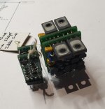
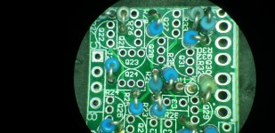
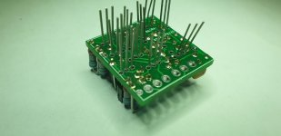
These are essentially the same as the steampunk one with the obvious difference of one being SMD fitting into the footprint of a DIP8 IC socket, and the second being jam packed thru hole but with TO126 output devices.
A hidden difference is that I have biased the output stage of the TO126 version at 20mA. yes the BD140s get toasty warm, but it IS class A so who is surprised?
On measurement, sorry the pics are at home, the TO126 version was significantly better than the SMD (SOT89) version.
I was actually surprised and would have bet on the SMD one given the matched pairs used throughout.
Into 5K the TO126 version was pretty much at the measurement floor of my distortion test set, with the gains and voltages I was using in this case it was -110dB on 3.2V peak to peak into 5kilohms. All the way from DC to 30kHz.
The SOT88 version was about 10dB worse. Huh????
I really want to dig in and find what the issue is with the SOT89 version or if it is just that output stage being lightly biased at about 10mA
Why did I start!!!!!
Since this older thread is back up, this is quite the feat of integration.  You wouldn't have needed to write that you're an engineer. 😉 (Using Altium would have been a massive hint, too...)
Going over the schematic in the first post:
If BC559s are anything like BC560s (Rbb' ~= 170 ohms for ON Semi parts), estimated input voltage noise density is about 3.1 nV/√(Hz). Input bias current would be somewhere around 1 µA, so the lower limit for current noise is around 0.8 pA/√(Hz) (ca. 0.7-1.0 pA/√(Hz)). Certainly decent enough values, and given the degenerated input stage I wasn't expecting class-leading e_n*i_n either.
(BTW, you're in good company with these BC559s - back in the day, that die was used for the NE5534A as well.)
You'd have room for higher current mirror resistors R26/27 (= less current noise there). The 68Rs are dropping almost nothing, I see little problem using e.g. 1k there instead.
I haven't had too much luck with these Darlington VAS' in simulation, common-mode distortion always seemed to be an issue. I guess it's because their native input impedance is actually quite high and only at HF does the compensation cap turn it into an I/V stage, while the other half of the input LTP sees the low-impedance diode. I don't see a good way of matching these wideband. (Things did seem to get substantially better if R29 was replaced by an ideal current source.)
Putting a diode across the compensation cap is actually considered somewhat problematic - while it does speed things up on paper it causes some unwanted side effects. Now where did I read that again...
 You wouldn't have needed to write that you're an engineer. 😉 (Using Altium would have been a massive hint, too...)
Prolly that. It is a SE Class A output after all. But if there are differences other than the output Qs it's hard to say for sure.A hidden difference is that I have biased the output stage of the TO126 version at 20mA. yes the BD140s get toasty warm, but it IS class A so who is surprised?
On measurement, sorry the pics are at home, the TO126 version was significantly better than the SMD (SOT89) version.
I was actually surprised and would have bet on the SMD one given the matched pairs used throughout.
Into 5K the TO126 version was pretty much at the measurement floor of my distortion test set, with the gains and voltages I was using in this case it was -110dB on 3.2V peak to peak into 5kilohms. All the way from DC to 30kHz.
The SOT88 version was about 10dB worse. Huh????
I really want to dig in and find what the issue is with the SOT89 version or if it is just that output stage being lightly biased at about 10mA
Going over the schematic in the first post:
If BC559s are anything like BC560s (Rbb' ~= 170 ohms for ON Semi parts), estimated input voltage noise density is about 3.1 nV/√(Hz). Input bias current would be somewhere around 1 µA, so the lower limit for current noise is around 0.8 pA/√(Hz) (ca. 0.7-1.0 pA/√(Hz)). Certainly decent enough values, and given the degenerated input stage I wasn't expecting class-leading e_n*i_n either.
(BTW, you're in good company with these BC559s - back in the day, that die was used for the NE5534A as well.)
You'd have room for higher current mirror resistors R26/27 (= less current noise there). The 68Rs are dropping almost nothing, I see little problem using e.g. 1k there instead.
I haven't had too much luck with these Darlington VAS' in simulation, common-mode distortion always seemed to be an issue. I guess it's because their native input impedance is actually quite high and only at HF does the compensation cap turn it into an I/V stage, while the other half of the input LTP sees the low-impedance diode. I don't see a good way of matching these wideband. (Things did seem to get substantially better if R29 was replaced by an ideal current source.)
Putting a diode across the compensation cap is actually considered somewhat problematic - while it does speed things up on paper it causes some unwanted side effects. Now where did I read that again...
I have never drilled into the finer details of input nose modelling. Mainly because the op amps I have built have been quiet enough that I have never been annoyed by the noise.
If I got annoyed, then I guess I would dust off the theory that I have not used for (well too long) and look into it.
The input bias current will be in the region of 1-2 uA. The DC Hfe of BC559C / 560C devices is pretty high, often in the 5-800 region.
I have used the buffered VAS in low voltage and high voltage applications with no overt problem. Well, there might be one or two cases of spurious oscillation that have been aggravated by this.
That diode is there to stop phase inversion on clipping. Again a consequence of Q28 being in there, on negative clipping the emitter follower can pull the base of Q31 up, resulting in some pretty funky negative clipping artefacts. So it is not about speed really - it is there for exception cases.
I really need to fine something to do with these devices. I nuilt a handful, and measured them. Once that intellectual itch had been scratched, by thoughts turned to "Damn these are big hot brutes, aren't they!".
I would have no hesitation in using them in one of the ludicrous number of audio systems I have - but the burning desire is satiated for now. 🙁
- Home
- Source & Line
- Analog Line Level
- Discrete Operational Amplifier (DOA) Thru Hole - STEAMPUNK version!

