Hi there,
apart from the huge interest in Studio Microphones, Measurement Microphones seem to be ignored in most Audio and Recording applications. Even though companies like GRAS or B&K build very high quality microphones. The reason is propably, that there isn't a compatibility to Audio devices (supply 200V Polarisation Voltage, +-60V Impendance converter supply, Preamplification/ Signal Processing and of cause the high costs for these precise microphones).
So I have come to the point, that it could be a very nice DIY project to build such a measurement Microphone. It should be a 1/2-Inch capsule by reason of a self noise, not higher than 16dBA. Still there are no 1/4-electret-capsules which offers such a low noise performance.
The microphone consists of the capsule. For Example the 40AF GRAS-capsule:
http://www.grasinfo.dk/documents/pd_40AF_ver_13_09_02.PDF
and an impedance converter which should be build in this project. The capsule needs a polarisation voltage of 200V and an high input and low output Impedance stage with a symmetrical supply of +-60V. This should be a discrete Impedance Converter. Classically this is realized with a JFET-input stage and a discrete voltage follower for low output impedance.
Before I post my first ideas I would like to wait for some posts and opinions and maybe someone out there in the Audio community, who has some experience with this topic.
I guess the realization will lead to problems, because of the input impedance design and parallel isolation resisters, which decrease the low frequency cut off.
Kind regards
Johan
Obviously the capsule needs the 200V dc polarisation voltage, but why does the buffer amp need +/-60V? You could use modern CMOS op-amps with bootstrapping of the 200V bias supply. The noise won't be as good as a simple FET stage, but it might be easier to get working properly.
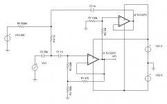
The capacitance of the B&K mics I have used is around 20pf, so the Zin of the buffer needs to be very high to get any LF performance. Attached is a TINA SPICE schematic of a buffer stage I might try. The simulation shows very good performance, but you would need to use PTFE boards to build it on!
The capacitance of the B&K mics I have used is around 20pf, so the Zin of the buffer needs to be very high to get any LF performance. Attached is a TINA SPICE schematic of a buffer stage I might try. The simulation shows very good performance, but you would need to use PTFE boards to build it on!
Attachments
Alternatively, you might think of using the capacitance of the microphone capsule as part of an L-C oscillator, which will get FM modulated by the audio signal. A PLL could demodulate the FM. I know B&K had such designs for recording earthquake rumbles, but I've never used an FM measuring mic i/f myself.
Measurement Microphone
Hi there,
thanks for your reply! I heard of the FM-Modulation technique, to have very good linearity. But I think it is to much RF design for a
DIY-Project. Epecially the lack of RF-Measurement equipment leads to problems.
So back to the Audio Circuit. Your Bootstrap-Circuit is an interesting impedance converter. Using the voltage divider R1 and R2 to lowers the current through R3 and bootstrapp the impedance to (approx.) Zin = R3 * (R2/R1) = 4,68 Gig Ohm. I used this circuit with a Capacitor in series to R1 to get better Offset-Current behaviour. The Offset-voltage over R3 and R1 is amplified by the open loop gain. When using FET-Op amp it mght work and you don't have to use a quite huge capacitor. The simulation looks good. Do you think there can occure other problems by reason of the offset current flowing through R3 and R1?
Because of the use of FET OP-AMP the noise performance isn't the best. This gives good reason to compare it to a discret impedance converter.
The most commercial impedance converters have a voltage supply of +-28V to +-60V. Using the GRAS-capsule and having the highest possible preasure Level of 150dBSPL (I know this is definetelly not practical value, especially not for audio, but this is what the most specs of impedance converter show) you get a peak-Voltage of 45V.
Here is a basic circuit of a condenser microphone:
It is a classical IC-FET-stage with a Voltage-Feedback over the Capacitor C3 and C4. The input section is very critical, because the high impedance can lead to problems, when isolation resister shunts the 1GOhm. I am not sure about the noise performance of this circuit. I gues the noise of the 1GOhm resister is low pass Filter by the 470pF.
What happens when the isolation resisters shunt the 1GOhm? In measurements it looks like 1/f-noise.
The ouput transformer is replaced by a bjc-transistor as impedance converter.
Cheers
Measurement Microphone
So one more try... I have problems with loading up jpeg files. Maybe the file size was to big.
Another technical comment. What do you think of the voltage feedback? I saw a lot of schematics without this feedback. For the input it works like a miller capacitance, which shunts the resistor. For the ouput it decreases impedance which is good when using an transistor in Collector circuit.
kind regards
Attachments

The linkwitzlab dot com website has a measurement mic project buried deep in the website somewhere which uses a Panasonic electret (I think) mic capsule bought at Digikey for about $3 if I remember correctly. Linkwitz says the built in FET is biased wrong and he shows how to modify that. Linkwitz is pretty sharp, so I have to assume that this mic and the preamp he designed for it (very simple) is actually plenty good for most uses.
- Status
- Not open for further replies.
- Home
- Live Sound
- Instruments and Amps
- DIY 1/2-inch Measurement Microphone