input: 4 x optical SPDIF
output: 1 x optical SPDIF
What should I buy? Or should I just buy that one for $60 of amazon--premade?
I'd like to integrate it into a DIY preamp though--so leaning towards diy.
Thanks.
output: 1 x optical SPDIF
What should I buy? Or should I just buy that one for $60 of amazon--premade?
I'd like to integrate it into a DIY preamp though--so leaning towards diy.
Thanks.
Why do you need optical out?
It would be difficult to switch light. I'd imagine the commercial ones convert to spdif to switch and back to tos to output. The actual tos receiver (connector) will output spdif on 2 of it pins. You could use relays to select which input you require.
It would be difficult to switch light. I'd imagine the commercial ones convert to spdif to switch and back to tos to output. The actual tos receiver (connector) will output spdif on 2 of it pins. You could use relays to select which input you require.
I need optical out because i have it feed into a dac that has an optical input. Well it also has a coaxial input (you can toggle switch it).
4051 style cmos switch or TTL version of 8in 1out mux chip.
its what I use for my spdif switch 😉
either one works; I tried the analog switch and the ttl switch and both work fine for spdif speeds.
make sure you get 5v toslink blocks and not 3v ones! they make 2 kinds so be sure.
(my spdif switch is controlled by i2c and remoted from another preamp. if you are not in a hurry, you can wait for a board run for my project).
input: 4 x optical SPDIF
output: 1 x optical SPDIF
What should I buy? Or should I just buy that one for $60 of amazon--premade?
I'd like to integrate it into a DIY preamp though--so leaning towards diy.
Thanks.
DIY? Well then, here's the thread when I built mine: http://www.diyaudio.com/forums/digital-line-level/136524-diy-dac-input-switchingon-budget.html. Somewhere in it, you'll find a link to a website with the design that was the inspiration for my own concoction, skip to post #37 of that thread. I use it every day and it works fine.
I made one with two coax in, two optical in, one optical and one coaxial out.
Should be easy to modify to your needs, though...
Last edited:
I'd be interested in a comparison between a digitally switched version and a mechanically switched one. I tend to lean towards the latter option eliminating on chip crosstalk. I accept that using mechanical switches has it's own issues, but I like the idea of the complete isolation.
Wouldn't there also be crosstalk in a switch?
I don't think running independent relays to switch 4 inputs to a single output would suffer from crosstalk. Each input would be completely mechanically isolated from each other. As stated there are other considerations such as contact resistance, size and more complex switching to control the relays. I'd still chose this option over a single chip acting as a switch with all signals present on die at all times.
Optical SPDIF doesn't always behave as you might think,
http://www.diyaudio.com/forums/digital-line-level/157831-optical-splitter-used-combiner.html
3 way switches,
http://www.diyaudio.com/forums/digital-line-level/157831-optical-splitter-used-combiner.html
PRO SIGNAL|PSG00950|3-WAY OPTICAL SELECTOR SWITCH | CPC Products&MER=e-bb45-00001001
http://www.diyaudio.com/forums/digital-line-level/157831-optical-splitter-used-combiner.html
3 way switches,
http://www.diyaudio.com/forums/digital-line-level/157831-optical-splitter-used-combiner.html
PRO SIGNAL|PSG00950|3-WAY OPTICAL SELECTOR SWITCH | CPC Products&MER=e-bb45-00001001
Optical SPDIF doesn't always behave as you might think,
http://www.diyaudio.com/forums/digital-line-level/157831-optical-splitter-used-combiner.html
3 way switches,
http://www.diyaudio.com/forums/digital-line-level/157831-optical-splitter-used-combiner.html
PRO SIGNAL|PSG00950|3-WAY OPTICAL SELECTOR SWITCH | CPC Products&MER=e-bb45-00001001
I'm guessing those are using a prism to reflect the light much the same way that a projector will combine the separate Red, Green and Blue displays into a single image. Not convinced a cheap plastic prism is the best way to go 😉
What about something like this?
DIY input selector
You only need to use 1 of the channels for the SPDIF. Any TOS receiver on the input will work.
Last edited:
I'm guessing those are using a prism to reflect the light..............
Perhaps 🙂
Once you decide to convert the optical back to electrical there are many possibilities for switching using something like linuxworks suggested earlier.
I bet even a simple single FET (one per Toslink receiver) could be made to work, or even switching the supply to each receiver as needed depending on what the outputs did with no supply (diode gating ?). Loads of posibilities.
heh - even LDRs could be switch elements. not sure what a signal looks like out of them, but they are 'all the rage' these days and you will get more hits if you work LDRs into your design (half lol).
relays are fine, imho. noisier than solid state at switch time but fine for RF use if you use the right relays.
I did have some bleed thru issues with an analog mux chip. I did not spend much time on it and I think it would be solvable easily but I opted to play with TTL switch chips instead and they are working just fine for me.
if you want to have a laugh, look at my 'hey, it works' hack:
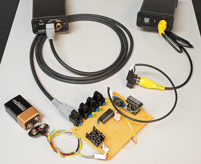
that has one coax-in (yellow rca cable thing going into a pulse trafo), 3 opto in and 1 opto out (room for 1 or 2 coax outs, too). that questionable chip carrier device (lol) is where I started out using a one approach but either ran out of that chip or abandoned it and went with a different one. I did not want to rework that board so I reworked it at the socket level. ha!
when I redid things, I made it a bit prettier:

that's an analog mux chip and it has lots of headers for remotely mounted toslinks or coax-ttl inputs. the large red connector was for the address select and I believe power, too. the 3pin in the foreground was the toslink output (pwr+data). the 4 in a row were toslink inputs. white molex was a 'courtesy power-thru' for powering remote boards (or cpus).
this was a sample front-end board for dual coax-in:

2 white on left are 2 coax ins. 2 red on right are 2 ttl level outs. white on right is power in. chip is 9637 diff line receiver which works great as a way to receive the coax (or even aes) input and convert to ttl out.
you can use the same kind of scheme (9638, I think) for sending from ttl to coax or aes out.
relays are fine, imho. noisier than solid state at switch time but fine for RF use if you use the right relays.
I did have some bleed thru issues with an analog mux chip. I did not spend much time on it and I think it would be solvable easily but I opted to play with TTL switch chips instead and they are working just fine for me.
if you want to have a laugh, look at my 'hey, it works' hack:
that has one coax-in (yellow rca cable thing going into a pulse trafo), 3 opto in and 1 opto out (room for 1 or 2 coax outs, too). that questionable chip carrier device (lol) is where I started out using a one approach but either ran out of that chip or abandoned it and went with a different one. I did not want to rework that board so I reworked it at the socket level. ha!
when I redid things, I made it a bit prettier:
that's an analog mux chip and it has lots of headers for remotely mounted toslinks or coax-ttl inputs. the large red connector was for the address select and I believe power, too. the 3pin in the foreground was the toslink output (pwr+data). the 4 in a row were toslink inputs. white molex was a 'courtesy power-thru' for powering remote boards (or cpus).
this was a sample front-end board for dual coax-in:
2 white on left are 2 coax ins. 2 red on right are 2 ttl level outs. white on right is power in. chip is 9637 diff line receiver which works great as a way to receive the coax (or even aes) input and convert to ttl out.
you can use the same kind of scheme (9638, I think) for sending from ttl to coax or aes out.
I don't think running independent relays to switch 4 inputs to a single output would suffer from crosstalk. Each input would be completely mechanically isolated from each other. As stated there are other considerations such as contact resistance, size and more complex switching to control the relays. I'd still chose this option over a single chip acting as a switch with all signals present on die at all times.
Ah, a switch used to control relays. Obviously, used that way, crosstalk wouldn't be an issue.
Given the fact that there are relays that can handle signals going into the GHz range, I see no reason why you couldn't use relays to switch between SPDIF sources.
I built my SPDIF switch like I did mainly because I had access to a pre existing design I could easily tailor to my needs and that used the same components that we have in surplus stock at work. The only parts I had to buy were the TORX and TOTX module(s).
Crosstalk was never something I thought about. If I had, I would probably still have gone for the multiplexer as I use it for my less than high end sources only.
Crosstalk with a TTL multiplexer is low enough not to be an issue in normal operation. Don't know if it has any affect on jitter, though...
Last edited:
have another laugh on me 😉
I ordered some 1:1 balun transformers to see how they'd work in TTL to coax (or aes3) conversion. when the order arrived, this is what fell out of the envelope:

lol! I had not checked the size and was expecting something a bit bigger 😉 something that I could just solder to air-wire style.
well, they were only $1 each. not sure if I'll ever find out if they work or not but they are rated up to the 800mhz range at about 1db down.
I ordered some 1:1 balun transformers to see how they'd work in TTL to coax (or aes3) conversion. when the order arrived, this is what fell out of the envelope:
lol! I had not checked the size and was expecting something a bit bigger 😉 something that I could just solder to air-wire style.
well, they were only $1 each. not sure if I'll ever find out if they work or not but they are rated up to the 800mhz range at about 1db down.
nothing is impossible. have 1 or 2 beers and things like this can materialize:


scary soldering on halloween. boo! 😉
I doubt I'll do this again, though. do you have ANY IDEA how hard it is to find 75ohm hot melt glue on halloween night?
scary soldering on halloween. boo! 😉
I doubt I'll do this again, though. do you have ANY IDEA how hard it is to find 75ohm hot melt glue on halloween night?
Nice work!
Definitely avoid strong coffee, if you have to do this... 😉
One down, three to go... 😀
Definitely avoid strong coffee, if you have to do this... 😉
I doubt I'll do this again, though.
One down, three to go... 😀
Last edited:
Not a DIY solution.
Dear all,
Now some TOSLINK SPDIF switches exist in Europe. I just sent an order in for this one.
InLine Toslink Audio Umschalter 4 zu 2 4x Toslink Buchse Eingang auf 2x Toslink Buchse Ausgang mit Fernbedienung
Which for people who have less German than me, (mines getting better slowly) means "InLine" Toslink Audio Switch 4 to 2, 4 Toslink inputs and 2 Toslink outputs.
I saw a very similar (possibly the same) device for sale on amazon.com and amazon.de. I hope they are all the same as the amazon.com one states it does 192Khz 24 bit signals but could not find this on the German version.
Regards
Owen
You forgot to translate the "mit Fernbedienung" bit, which means "with remote control", not bad for a price of less than € 38.
But only if they were ever to sell a version that also has coaxial inputs/output would I be interested.
But only if they were ever to sell a version that also has coaxial inputs/output would I be interested.
Last edited:
I'm doing some work on the nice wm8805 chip right now. it will go up to 192k, it dejitters and it accepts coax natively. you can even set some bits in the reciever to run at 3.3v levels (its a 3v chip) or at spdfi half-volt levels.
if I can get my arduino to talk to it and select inputs, etc, I'll base my spdif switch box on that. I do plan to make at least one run of boards available for diy once I get things working.
if I can get my arduino to talk to it and select inputs, etc, I'll base my spdif switch box on that. I do plan to make at least one run of boards available for diy once I get things working.
- Status
- Not open for further replies.
- Home
- Source & Line
- Digital Line Level
- diy Optical SPDIF Switch?