Hello everyone! I recently built a small sound system in my office with passive Edifier P12s and an old subwoofer, powered by a Fosi Audio BT30D. My sources are an Echo Dot with a aux jack to RCA cable as well as an Audio Technica AT-LP60X-BK turntable. It works and sounds great, but my the BT30D only has one set of RCA jacks, so whenever I want to listen to a record instead of streaming music, I have to open my cabinet and manually switch the RCA jacks.
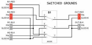
To that end, I need an RCA switch. I was originally looking at the SOLUPEAK S1, but it's a bit expensive and it seemed like an easy enough project to build on my own. My biggest issue is that I'm not sure whether I should tie my ground together, or if I should switch them along with the RED and BLK lines. I've attached two schematics to illustrate the two different designs. I've seen several threads about doing exactly this, and it seems like most people use common grounds and only switch the RED/BLK lines. I don't think that would cause any issues, but I'm very far from an expert on electronics/audio equipment.
So, diyAudio, what do you think? Should source grounds be common or separately switched? Please provide some reasoning as to why you believe it should be one way or the other.
Attachments

I'm going to say common grounds not switched. Why... because that is the way 99.9% of such things are made and they work without issue.
Switched grounds can sound like a good idea but unless done correctly and reliably will cause trouble. They need to make before break. If that doesn't happen then you will get tons of hum/noise for a fraction of a second which you, your speakers and your amp will not like.
That's my take on it 🙂
Switched grounds can sound like a good idea but unless done correctly and reliably will cause trouble. They need to make before break. If that doesn't happen then you will get tons of hum/noise for a fraction of a second which you, your speakers and your amp will not like.
That's my take on it 🙂

Hey Mooly, I appreciate the quick reply! Are the grounds the only connection that need to be "made before broke" or would all of the connections require that if I went with the switched ground schematic?
It certainly sounds like it would be more challenging to create, but are there any benefits to a switched design?
It certainly sounds like it would be more challenging to create, but are there any benefits to a switched design?
In theory you could argue that switching grounds properly could be better because it would totally isolate all other components and so remove any ground induced noise/hum loops etc but as mentioned 99.9% of audio gear does not do this and it all works just fine.are there any benefits to a switched design?
The ground is the one that must be make before break. The signal connection isn't as important. If it does make before break then all that happens is that you get both sources in parallel for a fraction of a second and so hear both if both are playing. Which wins out for that instant depends on the output impedance of each source.
I wouldn't complicate it, just make it in the time honoured fashion 😉 and save the switched grounds for precision lab gear measuring down to the nth degree.