Diy speaker kit has optional "impedance correction" parts for tube amplifiers?
The speaker kit I want to build (4ohm, 90dB) includes an optional set of parts (R,L,C) for "impedance correction" (? Translated from german...) For use with tube amplifiers.
- what does this do?
- since I might or might not be using a tube amplifier later on, should I include it in the build?
- since Im not using a tube amplifier right now, would including it be detrimental to performance right now?
It's just a few bucks in parts, so if it's not detrimental to performance when NOT using a tube amp I'd rather include it just in case - I might fancy a tube amp later on..
Last edited:
The RLC impedance correction linearizes the impedance curve, typically smoothing the peaks. Tube amps (not all tube amps are the same) can react to big impedance swings by sounding non-linear, as if boosting or cutting certain frequency ranges. Hear often about "mellow" highs from tube amps?...
Since the LCR parts are no big expense, you could have them handy and try with and without. The LCR "circuit" can be attached to the speaker terminals from the outside, across + and - , so easy enough to implement.
Try it with SS amps as well, although they should in general be OK without. I guess it can't hurt.
Tube amplifiers are more troubled by loudspeaker impedance variations than transistor amps.
The impedance correction circuit is designed to smooth out any large variations in the impedance of the loudspeaker.
It is OK to include the circuit at the outset as it won't be detrimental to your transistor amplifier.
The impedance correction circuit is designed to smooth out any large variations in the impedance of the loudspeaker.
It is OK to include the circuit at the outset as it won't be detrimental to your transistor amplifier.
So if Im correct in theory all speakers should have this little addition for maximum amp compatibility?
Or doesn't it work quite like that?
Or doesn't it work quite like that?
You are correct! However, there are extra design costs involved as the location in frequency of the impedance correction circuit must be considered in relation to the loudspeaker crossover frequency.
This is why impedance correction is not normally incorporated into budget range speakers.
Best to regard impedance correction as not being essential but just the 'icing on the cake'.
This is why impedance correction is not normally incorporated into budget range speakers.
Best to regard impedance correction as not being essential but just the 'icing on the cake'.
The heart of the matter here is that SOME tube amps have very non-insignificant output impedance. You can envision this like a power resistor of a few Ohms placed in series with a solid state amplifier. This extra "resistance" comes from the particular parts used to construct the tube amp, usually the output transformer. The output impedance is captured by the spec called "damping ratio", which is almost never listed for tube amps.
Let's say that a hypothetical tube amp has an 8 Ohm output impedance. And let's say this amp is rated to deliver 20W into an 8 Ohm (nominal) load. A loudspeaker, without impedance compensation as part of the crossover network, is anything but "nominal" in its impedance. There are at least a couple of peaks that are usually on the order of several tens of Ohms. These happen around the driver resonance frequency, and because of crossover component reactances. Just go look at the impedance curve for some speakers that are published (in Stereophile tests, etc.) and you will see what I mean. Every speaker is different!
When you connect a loudspeaker with a lumpy impedance curve to a tube amp with a significant output impedance, you are essentially creating a voltage divider from the two impedances (amp and speaker). It's just like connecting two resistors between a voltage source and ground, except one of the resistors is changing the resistance up and down as a function of frequency. That's the loudspeaker. You might know from electronics that a voltage divider causes different voltage drops across each of the two resistances, depending on their relative resistance to each other. When the loudspeaker is 8 Ohms and the tube amp is 8 Ohms you get the rated power. But when the loudspeaker impedance increases to 40 Ohms it is actually getting MORE POWER at that frequency from the tube amp compared to the frequency where it is 8 Ohms, in fact the response might be +3dB there. Likewise, if the impedance of the loudspeaker drops to 4 Ohms at some frequency, the power delivered is about -3dB. So what happens is the POWER that the amp is delivering to the load as a function of frequency is changing up and down with the impedance curve of the loudspeaker. What happens is in effect like a tone control, and the larger the amplifier output impedance the greater the effect. This is why tube amp guys say that amp A made their system sound so much different that amp B. That's because it actually did!
One way to largely eliminate this effect is to use special passive networks as part of the crossover that remove the peaks from the loudspeaker impedance. When used in parallel with the loudspeaker driver(s) the paralleled impedance drops the peaks down to a value near the nominal or minimum impedance of the loudspeaker. Once the loudspeaker's impedance curve is more or less flat (the same value for all audio frequencies) then the tube amp's output impedance effect can become negligible depending on how well the impedance correction networks are implemented.
The impedance correction comes at a cost!
You pay for it in power dissipation, especially if you attempt to correct the lowest two impedance peaks. Those are always high wattage parts, and for good reason.
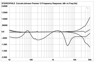
IMHO it is a worthwhile trade only for tubes. Take a look at a typical tube amp output vs. solid state into a simulated speaker load such as here:
You pay for it in power dissipation, especially if you attempt to correct the lowest two impedance peaks. Those are always high wattage parts, and for good reason.
IMHO it is a worthwhile trade only for tubes. Take a look at a typical tube amp output vs. solid state into a simulated speaker load such as here:
But isn't it true that most of the impedance correction circuits only correct for the high frequency peaks of the speakers? For example, in a 2-way, the impedance peaks often occurs around the xover frequency which is around 2 - 2.5khz so it may not dissipate power that much.
Below I post a typical impedance curve of a two way with a peak at around 2K. The RLC circuit would flatten the peak there.
Below I post a typical impedance curve of a two way with a peak at around 2K. The RLC circuit would flatten the peak there.
Attachments

Last edited:
Andy,
Yes, most circuits which I have seen only deal with the peaks in the higher range. I still feel 5 W wasted is 5 W wasted, not to mention additional parts. However, some attempt do do them all.
For a precise measure, you can simulate this with something like XSim and measure the power loss directly off the impedance correction components.
I believe, but I am not sure, that series crossover have less of an issue with this.
Best,
E
Last edited:
It's a sensitive area. It would be advisable even if the parts weren't smaller/cheaper. A DIYer probably wouldn't want to stop there.But isn't it true that most of the impedance correction circuits only correct for the high frequency peaks of the speakers?
Do you also use class D amplifiers?I still feel 5 W wasted is 5 W wasted
This should read - power sources and current sources ... than Voltage sources.Tube amplifiers are more troubled by loudspeaker impedance variations than transistor amps.
I use RCL in series and RCL in // to filter the woofer. If it is designed that way it is very smart to install it.
On other diy speakers I use a RCL in // only on the tweeter, the XO was designed for my tube amps!
On other diy speakers I use a RCL in // only on the tweeter, the XO was designed for my tube amps!
These are the measurements for the speaker I have in mind; can you tell from this whether or not it's useful to add the impedance correction..?
Attachments


Last edited:
What's missing is the amplifier output impedance as well as how much deviation you are willing to tolerate.
The phase angle seems high around the crossover region though.
Why don't you try it with cheap parts and see if you hear much of a difference. 🙂
Bet,
E
The phase angle seems high around the crossover region though.
Why don't you try it with cheap parts and see if you hear much of a difference. 🙂
Bet,
E
The full set of measurements is on this page:
Bausatz Samuel HQ – Heissmann Acoustics
I'm not very adept at reading the graphs yet 🙁
Bausatz Samuel HQ – Heissmann Acoustics
I'm not very adept at reading the graphs yet 🙁
Pygmy,
What I meant was, you need to know the amplifier to be sure of your answer. 🙂
Solid state amplifiers tend to have an output impedance in the tenths of ohms, so no problem. Amps with output impedance in the ohms range are going to be more reactive.
Best,
E
What I meant was, you need to know the amplifier to be sure of your answer. 🙂
Solid state amplifiers tend to have an output impedance in the tenths of ohms, so no problem. Amps with output impedance in the ohms range are going to be more reactive.
Best,
E
Poorly designed solid-state amplifiers may go into SOAR limiting at high volumes when the load is highly reactive, impedance correction also solves that problem. It also eliminates the (generally already small) effect speaker cable resistance might have on the frequency response.
By the way, nice to meet someone from my hometown here!
By the way, nice to meet someone from my hometown here!
Second-hand Marantz direct-drive turntable, home-made valve DAC (see Linear Audio | your tech audio resource), Sony ST-SB920 tuner, old Technics cassette recorder, Pioneer DV-575AK CD/SACD/DVD-A player, home-made valve-based phono preamplifier (see Linear Audio | your tech audio resource), home-made solid-state main amp (see Electronics World February 1996) and two Quad S-2 bookshelf loudspeakers. I used to have second-hand Quad ESL-63 electrostatic loudspeakers, but our present cat liked to climb on them and he wasn't always careful when he jumped off. How about you?
- Status
- Not open for further replies.
- Home
- Loudspeakers
- Multi-Way
- Diy speaker kit has optional "impedance correction" parts for tube amplifiers?