Hello everyone! I bought an mystery Eico ST 70 from ebay. Was missing an output tube and was all original. I checked all the tubes and ended up replacing all of the output tubes. Over the next few weeks I did a (what I believe and hope) to be a very nice recap job, took many photos and worked slowly and even checked as a I went along with the schematic. Anyhow, tonight I brought it up on the variac, little by little and sure enough the draw was rising and rising and pop, 3 amp fuse gone. So being a novice I referenced my instruction manual and see that if I blows the fuse with and without the rectifier in (which I tested this and statement is true) then it has to be a short in the line cord, in the two aux AC jacks, in the primary or high voltage secondary windings of the main transformer, internal or external.
Okay, deep breath, so would the best thing to do is to remove the main transformer, or just separate it from the rest of the device and slowly apply voltage and see if it starts to pull amps again?
Thank you all in advance!
Okay, deep breath, so would the best thing to do is to remove the main transformer, or just separate it from the rest of the device and slowly apply voltage and see if it starts to pull amps again?
Thank you all in advance!
Do not remove the transformer.
Remove all the tubes and replace the fuse. Plug in the amp and see if the fuse holds. If so, the power transformer should be ok.
With all tubes still out, check the bias DC voltage for proper range of adjustment, roughly -20V to -60V.
Then post back here.
By the way, a short in the filament or bias circuit could indeed blow the fuse without the rectifier tubes (or any tubes) in place.

okay, I will do this but just for my learning information, will this test the integrity of the tubes for shorts or will this rule out the possibility of shorts after the tubes? or both 🙂
Okay, drew it up to 120 slowly on my BK 1655a and I got to 120 and the fuse didn't blow but the main transformer is sizzling like pop rocks and getting hot!
Ok, that sounds like HV leakage. Remove power and unplug the amp.
Probably the best thing to do now is to disconnect all transformer wires except for the primary AC input.
Tape all the wires off in a safe manner. Remember there is rather high voltage on some of the wires.
Be very careful. Repeat the Variac test. If you get the same behavior, the transformer is bad.
Yep! When I heard that I turned it off!
Okay I will try that now, if it does confirm to be bad Is it worth it to take it apart, can anything be done, or start hunting for a donor unit?
Okay I will try that now, if it does confirm to be bad Is it worth it to take it apart, can anything be done, or start hunting for a donor unit?
okay, I will do this but just for my learning information, will this test the integrity of the tubes for shorts or will this rule out the possibility of shorts after the tubes? or both 🙂
Removing all tubes eliminates the possibility of either a bad tube, bad filter capacitor, malfunctioning bias circuit, or wrong bias adjustment,
all possibly causing the fuse to blow.
Remaining possibilities without any tubes are: bad transformer, shorted wiring in one of the secondaries, shorted bias circuit,
shorted primary wiring.
What do you mean by that, no heat/noise problem with all secondary wires taped off?
That's good, maybe the transformer is ok after all.
If so, reconnect one secondary at a time, starting with the filament windings.
1 - green pair
test
if ok, leave connected
2 - brown pair
test
if ok, leave connected
3 - yellow pair
test
if ok, leave connected
Post back here if all 3 of these windings give no problem.
Don't go any farther just yet. The rest is more dangerous.
Sure, that's what we're here for.
You gotta short in the wiring or in some component.
You gotta short in the wiring or in some component.
Okay so update: brown and green, one by one are fine. The 5 left are the ones that go to the rectifier socket and a blue one, that goes to a diode and cap.. Will do yellow now, holding off on red..

Photo is missing.
If I count right, you should have 4 wires left.
red - HV to rectifier socket
red - HV to rectifier socket
red-yellow - center tap to ground
blue - bias tap to diode cathode
If you have a short at the diode tap, that could be damaging to the HV winding.
Check the diode for normal pn junction behavior on your DVM if it is a silicon type.
If the diode is shorted, replace the diode and all 3 capacitors in the bias circuit.
If this is a selenium rectifier, the two lugs could short together and short out the diode.
If this is the problem, replace all 3 bias capacitors.
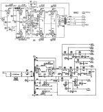
Note the schematic, at least the one that I have, has the +/- diode marking reversed.
You want a negative DC voltage from the diode output.
If I count right, you should have 4 wires left.
red - HV to rectifier socket
red - HV to rectifier socket
red-yellow - center tap to ground
blue - bias tap to diode cathode
If you have a short at the diode tap, that could be damaging to the HV winding.
Check the diode for normal pn junction behavior on your DVM if it is a silicon type.
If the diode is shorted, replace the diode and all 3 capacitors in the bias circuit.
If this is a selenium rectifier, the two lugs could short together and short out the diode.
If this is the problem, replace all 3 bias capacitors.
Note the schematic, at least the one that I have, has the +/- diode marking reversed.
You want a negative DC voltage from the diode output.
Last edited:
0.421 forward and OL reverse
Schematic shows the cathode to the blue wire so i think I have it wired correctly, this was a new diode by the way. Also, the cap there, schematic shows + to the gnd where the red-yellow from transformer go, wired that correctly.
Let me disconnect that blue wire, see where it runs, maybe that is something?
Okay blue wire disconnected, still a short, must be bad cap (it was new too) or that diode, right I mean what else can it be, we pretty much narrowed it down.
The blue wire is the HV bias tap, and goes directly to the HV winding.
I would replace both the diode and the capacitor regardless. Observe polarities.
Anode of diode goes to (-) capacitor lead.
Cathode of diode goes to blue wire only.
Do look for other shorts downstream at connections to R99 and R101.
I would replace both the diode and the capacitor regardless. Observe polarities.
Anode of diode goes to (-) capacitor lead.
Cathode of diode goes to blue wire only.
Do look for other shorts downstream at connections to R99 and R101.
Attachments

WOW okay, you won't believe this....well I do not mind making myself look like an idiot, here is what I did, look close at that picture!!!! I am grounding the tap that the blue wire goes to!!!! Ugh, so sorry, let me reconnect and we can see!
I won't soon live this one down, sorry! But hey what a great lesson in chasing and troubleshooting!
I won't soon live this one down, sorry! But hey what a great lesson in chasing and troubleshooting!
- Home
- Amplifiers
- Tubes / Valves
- Eico ST70 restore - short