An electret mic doesn't need external power to bias the transducer element (bias is provided by the electret material), but does require power as most have a built-in JFET preamp stage. This is vs. legacy condenser mics (tube) which needed supplies for element bias, heater and plate supply for the internal tube.
But looking at a schematic for a mini electret mic, you can see that there's no bias network for the internal FET, only a load resistor in series with the Vcc. How does it manage a reasonable, low-distortion output if there's no bias network? Won't any + excursion drive gate current?
I posted a similar query in the 'parts' forum, to no reply. I'm reposting it here, as it seems we have a few well-educated engineers looming around.
Single-Supply, Electret Microphone Pre-Amplifier
Dan.
An extremely high resistance, RG, may be included to
bias the gate of the JFET.
Dan.
The P-N junction is somewhere between drain and source, so it is already biased by the voltage applied to the drain. Sure, too high SPL can open it, but back in 2008 on AES convention I met people who demonstrated their super-compact subwoofer with an electret microphone inside used as a pressure sensor. It did not clip, according to them!
Dan,
Interesting, thanks for that. Here's the relevant figure from the doc:

They state that Rg "Might be included", but no mention as to when / why it might be required. So how would it work, in any case? Same concept as grid leak bias on a vacuum tube?
Interesting, thanks for that. Here's the relevant figure from the doc:
They state that Rg "Might be included", but no mention as to when / why it might be required. So how would it work, in any case? Same concept as grid leak bias on a vacuum tube?
If the resistor is omitted then presumably it relies on leakage current through the mike element for bias. In either case gate bias is 0V, so there is a bias network. The junction will normally be somewhat reverse biased, so no gate current.
And even if it were forward biased at some part of the cycle, being "forward" is not enough, that voltage should also be higher than natural PN junction barrier voltage .... not sure raw unbuffered electret membrane can supply that much voltage unless excited by a starter pistol or inside a floor drum.
There is a difference between "necessary" and "sufficient" 🙂
There is a difference between "necessary" and "sufficient" 🙂
If the resistor is omitted then presumably it relies on leakage current through the mike element for bias. In either case gate bias is 0V, so there is a bias network. The junction will normally be somewhat reverse biased, so no gate current.
Presumably.. 😉
It would be helpful to know the amplitude of the electret bias.. again, is it uV, mV? If it's in the few tens or hundred of mV, that alone might be enough to do the trick.
Now in the case where Rg +is+ present, how does Rg serve to bias the FET? What's the mechanism? Do FETs have the same space-charge effect as tubes, such that a 10M on the gate will provide sufficient bias? FETs are depletion mode, so normally 'on' so to speak.
Later in the same document, we find this image:

In addition to the FET, there are two small SMT parts on that board, but I can't quite tell where they are in the circuit. One may be Rg, but what's the other? I sure wish I had one of these to rip apart.. they're still in the post, though.
A clean capsule with a small JFET, even a GigaOhm of gate conductance will do.
Nearly all low-cost capsules just rely on leakage.
Nearly all low-cost capsules just rely on leakage.
If the resistor is omitted then presumably it relies on leakage current through the mike element for bias. In either case gate bias is 0V, so there is a bias network. The junction will normally be somewhat reverse biased, so no gate current.
No, there is no resistor there is another junction from the gate to source (you can actually measure for it) the drain to gate leakage of the FET forward biases the gate junction 100-200mV and it acts like a huge resistor ~2VT/Is. 2SK123 is an example of this special FET notice the operating current is more than Idss due to the slight forward bias. The extra diode prevents long recovery from overloads where the gate might get to a large negative voltage and have to settle back.
Take a FET and let the gate float and measure the Id it's easy, then touch the gate with your finger.
Last edited:
Electrician voltage sticks use such arrangement, ie the gate is connected to a 1" sensing wire in the tip of the probe end.Take a FET and let the gate float and measure the Id it's easy, then touch the gate with your finger.
Dan.
Take a FET and let the gate float and measure the Id it's easy, then touch the gate with your finger.
I'd sure like to, but I don't have any.. which leads into the next question.
What are the most common, useful types of Jfet for basic experimental work? Is there a universal workhorse 2N2222 or 2N3906/3904 of the Jfet world? I'm aware of the 2N7000, but that's an enhancement mode MOSfet.
A pack of 10 (cheap) mics showed up today, and I took the time to dissect one. They were sold as back-electret types, but based on the unit I took apart, they're the conventional diaphragm type, with a metallized diaphragm and a solid metal backplate. Why is it so hard to be informed and/or honest?
The unit I dissected had nothing other than the microphone elements and what is presumably a small FET on the board. There are no resistors, no caps. When powered from 3V DC -> 2k2 resistor, the element draws 470uA (0.47mA) which is very typical for this type of mic.
Good to know, that's all well and fine. But how do I find a "decent" back electret capsule? Not looking for hi-end here, but maybe $1-5 USD for a capsule vs. $0.10/ea as for these? Do I really need to make a huge jump in cost to get even a basic back-electret capsule? In case anyone is curious, I'm wanting to build a parabolic dish mic, to listen to insects, birds and other animals that might be hanging out on the shores of a lake. So I need a reasonable mic and a basic amp - which so far looks like it will be a simple LM386.
Any suggestions are welcome.
Last edited:
It usually takes 500 - 600 mV forward bias to get any appreciable current flow through a silicon junction. I think it would take an improbably loud sound to actually forward-bias the junction.It would be helpful to know the amplitude of the electret bias.. again, is it uV, mV? If it's in the few tens or hundred of mV, that alone might be enough to do the trick.
However, there is no negative feedback around the JFET whatsoever, so the JFET has measurable - maybe also audible - amounts of nonlinearity, and corresponding harmonic distortion, particularly for loud sounds.
Keep in mind, these mics were originally designed for use in telephones, telephone answering machines, cassette recorders (remember those?), and other similar consumer products. Ultra high fidelity was never part of the design specs.
Some years ago, there was a popular "mod" for electret mic capsules that involved cutting the PCB trace that grounds the JFET source to the capsule housing; with that cut, and two fine wires soldered on, you could now insert an external source resistor, connect the drain direct to your positive supply voltage, and operate the JFET as a source follower. No voltage gain, but lower THD.
Gate current is essentially zero, so the gate is at zero volts, even when Rg is in giga ohms. Valves leak far more electrons out of the grid than JFETs do. 🙂Now in the case where Rg +is+ present, how does Rg serve to bias the FET?
There were two-pin and three-pin electret mic capsules. The luxurious three-pin versions included the JFET drain resistor inside the mic capsule. I'll bet that's the second SMT part in your photo....two small SMT parts ... One may be Rg, but what's the other?
The JFET source, JFET drain, and far end of the drain resistor are brought out to the three pins on the back of the capsule. So, with these three-pin capsules, you hook up one pin to the positive supply, another to ground, and the third is your audio signal.
The two-pin versions didn't give you the onboard drain resistor, so you had to wire up an external one.
Please don't rip one apart - they are rapidly becoming extinct, thanks largely to Apple Corp's obsessive pursuit of absurdly thinner and thinner 'phones.I sure wish I had one of these to rip apart..
You see, some years ago, electret mics were everywhere, with one in every phone, cellphone, and answering machine - and there were hundreds of millions, maybe even billions of these devices made each year.
Then Apple switched to smaller and thinner MEMS microphones in their devices, so that they could make their fondle-slabs a hair thinner, and therefore Even Betterer (TM). Other phone-makers rushed to follow suit, and the electret mic suddenly found itself in the same position as buggy-whips did in the early days of the automotive revolution.
At this point, it would appear that old-fashioned electret mics are actually better microphones than shiny new MEMS microphones. Decent electret mics are not only remarkably cheap, they also have remarkably wide and flat frequency responses, considerably wider and flatter than the MEMS mics that I've looked up data sheets for.
But Apple Corp. routinely places image above substance, so of course, they threw out the better microphones and replaced them with the thinner ones. Anorexic phones rule! 🙄
There are now MEMS microphones with integrated A/D converters and associated support and conditioning circuitry on the same chip as the actual MEMS cantilever. These things spit out a microprocessor-friendly digital audio signal straight from the microphone. Perfect for the DSP chips in the cellphone to work with.
Clearly, the electret mic is not about to make a comeback. It seems the really good ones ( like the remarkably accurate $2 Panasonic WM61A ) are already extinct. If you find any, they will be NOS.
There may still be some no-name Chinese companies making lower quality electret mics for whatever remaining market still exists; I don't know.
-Gnobuddy
Looks like you posted while I was composing my last reply.how do I find a "decent" back electret capsule?
Unfortunately, good electret mics are now either endangered or extinct. Perhaps you'll get lucky and find some NOS ones on Ebay?
-Gnobuddy
Looks like you posted while I was composing my last reply.
Unfortunately, good electret mics are now either endangered or extinct. Perhaps you'll get lucky and find some NOS ones on Ebay?
-Gnobuddy
Check out the micbuilders Yahoo group there are numerous low cost recording mics still made that use electret capsules sources for good ones for DIY come up there all the time.
A pack of 10 (cheap) mics showed up today, and I took the time to dissect one. They were sold as back-electret types, but based on the unit I took apart, they're the conventional diaphragm type, with a metallized diaphragm and a solid metal backplate. Why is it so hard to be informed and/or honest?
You can't tell that easily both have to have a diaphragm. The backplate only needs a thin layer of electret coating same with the back of the diaphragm. One or the other has to have the electret or it won't work.
I dunno, the MEMS mics have gotten extremely good and more R&D has gone into them than ever went into electret capsules. Check out the Knowles products- Knowles :: Microphones I've measured one of the their special high frequency mics out to way over 100 kHz, for those that want to downconvert insect noises and such.
I'm sure they're getting better with time. However, MEMS microphone technology has a few inherent disadvantages, and it may take a while before engineering cleverness finds a way around them:I dunno, the MEMS mics have gotten extremely good and more R&D has gone into them than ever went into electret capsules.
- Silicon (MEMS cantilever material) is much denser than the plastic used in electret microphones.
- A tiny silicon cantilever has very high mechanical Q, like a tiny tuning-fork. By contrast, plastic electret diaphragms have high mechanical losses, and low mechanical Q.
- Silicon is inherently a very stiff material.
Meantime, the high stiffness of silicon tends to roll off the deep bass response in MEMS microphones.
So MEMS mics typically have limited deep bass response, and a peaky treble response, often not extending beyond 10 kHz.
Thanks for the link! I checked out the first one in the list, and, sure enough, you can see both the problems I just described.Check out the Knowles products- Knowles :: Microphones
At the high frequency end of the graph (which is only 10 kHz), you can see the beginnings of a poorly controlled mechanical resonance (peak in the frequency response). The provided frequency response graph (attached) cuts off at 10 kHz, but the frequency response is already rising towards a peak somewhere beyond the right edge of the graph.
Note also that, at the bass end, this mic is already 2 dB down at 100 Hz. Deeper bass will be rolled off even more.
Of course 100 Hz to 10 kHz is more than adequate for transmitting reasonably good quality speech, so this MEMS mic is certainly good enough for a 'phone. But it isn't as good as the better electret microphones used to be.
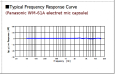
For reference, I'm also attaching a screenshot of the frequency response curve Panasonic provided in their old WM-61A electret microphone datasheet.
The old-technology WM-61A electret mic frequency response extends out beyond 15 kHz at the high frequency end, with extremely minor wiggles. At the bass end, it's ruler-flat down to 50 Hz, where the graph ends; clearly, the actual microphone frequency response goes well below 50 Hz, because there is no bass roll-off at all at 50 Hz.
For recording passable-quality speech, either microphone would be adequate. But the old Panasonic electret is actually good enough for high-quality music recording, and for use as a poor-mans measurement microphone. Amazing, for a $2 device!
That's impressively high! Do you happen to remember what the corresponding bass end of the frequency response was? Was the entire frequency response above the (human) audible spectrum, or was this mic capable of picking up bass as well?I've measured one of the their special high frequency mics out to way over 100 kHz, for those that want to downconvert insect noises and such.
-Gnobuddy
Attachments

Now here is something interesting. The 2SK1109 and similar are commonly used inside of ECM capsules. From the 2SK1109 datasheet, take a quick look at this snip:

Note that this specific JFET, purpose-made as an impedance converter for an ECM, has an internal gate resistor as well as a diode pair clipping the input to some low level (0.30-1.0V?). This might well answer a few questions. Note that they term it an 'impedance converter,' rather than a preamp - as it is often described.
Full datasheet is here: http://www.firstpr.com.au/rwi/mics/2009-09-b/2SK1109-datasheet.pdf
Last edited:
- Status
- Not open for further replies.
- Home
- Live Sound
- Instruments and Amps
- Electret condenser mics