Hi
the base of this amp is the huge thread about :
the amp was modified by XRK and others and use no Lateral MOSFET --> therefore well known IRFP240 and IRF9240 are used.
here are some examples and comments:
here
here:
the base of this amp is the huge thread about :
100W Ultimate Fidelity Amplifier
these is the thread for all fans of the Vertical brother of APEX FX8 done by XRK and prasi:the amp was modified by XRK and others and use no Lateral MOSFET --> therefore well known IRFP240 and IRF9240 are used.
here are some examples and comments:
here
here:


Hello,
not much activity in here...
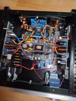
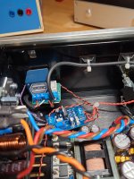
After some troubleshooting 3 amps are tested and running with 45 mA, only for testing. The fourth i have to test to in the next days. I want to built two Amps. At first a little amp with +-36 Volt voltage and 70 mA bias. I ordered a little amp case and built in. I like the case, but i dont need the pot really. I can stwitch it off.
For the first time i built a ssr delay in. No DC protection, only a timedelay of 7 sec after smps start. The smps is a 300 Watt connex smps. The aux output is +- 15 volt. With my little lm317 board i adjusted the positive aux rail to +12 volt to power one led, the ssr and the takamisawa relais. Later i will make a current measurement to make sure that the smps can deliver the nessesary current.
All cables are built in now and an i can make the bias adjusting later. To shorten the input i switch the pot off and shorten the input over rca post. The ssr is switching speaker -.
Okay...pictures
I wish you a merry chrismas...early, better as to late 🙂
not much activity in here...
After some troubleshooting 3 amps are tested and running with 45 mA, only for testing. The fourth i have to test to in the next days. I want to built two Amps. At first a little amp with +-36 Volt voltage and 70 mA bias. I ordered a little amp case and built in. I like the case, but i dont need the pot really. I can stwitch it off.
For the first time i built a ssr delay in. No DC protection, only a timedelay of 7 sec after smps start. The smps is a 300 Watt connex smps. The aux output is +- 15 volt. With my little lm317 board i adjusted the positive aux rail to +12 volt to power one led, the ssr and the takamisawa relais. Later i will make a current measurement to make sure that the smps can deliver the nessesary current.
All cables are built in now and an i can make the bias adjusting later. To shorten the input i switch the pot off and shorten the input over rca post. The ssr is switching speaker -.
Okay...pictures
I wish you a merry chrismas...early, better as to late 🙂
Attachments


Hi PEdda,
very nice work...yes i see that you like small housings.. 😉....well done.
i was busy to recycle 4 old amps which i shoot 2nd hand and try to get cheap housing - yes now i want to build a good amp with used parts...processing.
plus...i was building a ACA linear power supply: ACA linear power supply
and now i am ready with my first putting into operation of FH9 amps:
i use a small alu heat sink from a old AVR ...luckly i got 2 but they are very small. first test with 32V rail and 500mA was to hot and therefore i use a bigger heatsink but these AVR heat sinks are cheap made.
my target is reached, because the bigger heat sink can handle the voltage and current about the same as my actual setup on the FX8 = 750mA. stable.
my drivers (T2/T3) are not mounted on the big heatsink and got no heat over 1hour testing.
everybody who wants to build this amp please be carefully to contact the transistor T4 (BD139 -temp guard) with good thermal and mechanical contact to the heat sink.
additionally i start with the second amp, so 2 amp pcb are partly soldered. i sue a big 100µF nichicon muse theree. at my first set of amp i found a small 4,7µF wima cap.
over the holidays i try to implement these amp boards into a 2nd hand case.
I wish you and all guys here in the forum merry Christmas and a happy new year !
Attachments
-
 FH9 XRK mod_small_heatsink2.jpeg196.1 KB · Views: 252
 -
 FH9 XRK mod_6_.jpeg107.7 KB · Views: 253
 -
 FH9 XRK mod_5_muse input cap.jpeg297.4 KB · Views: 255
 -
 FH9 XRK mod_4_heatsink_compare.jpeg209.7 KB · Views: 262
 -
 FH9 XRK mod_3.jpeg184.9 KB · Views: 237
 -
 FH9 XRK mod___small heatsink.jpeg220.3 KB · Views: 275
Hi
i found a comment by XRK about changing the ceramic to film...
post 9933 in the big 100W ultimate fidelity amplifier thread
here:
One comment: try to put film caps in for the 100pF at the drivers instead of ceramic MLCC's unless NP0/C0G - it will improve the sound with lower distortion. Also, definitely out a film cap for the 330pF RFI input filter cap. That is definitely a source of improving the sound. They are subtle but taken together will improve the sound.
so next step for improvement?
chris
i found this thread...maybe it helps...for protection and delay:Good job Kleinhorn!
Congratulations.
What is your speaker protection board?
protection board
is that the one?
i would recommend 3U 400mm deep. space for work all inside!Hmmmmmmm how big has the heatsink/case have to be for 6 channels ?
Got an idea....
the FH9 pcb are very compact better then the FX8 bimo pcb
😉
Hmmmm... 6 channels and my dsp..... 3 Way full active loudspeaker..... Hmmmmm sounds like a plan
Hi...
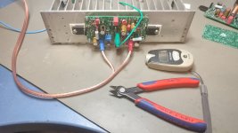
As i wrote..its no protection board, only a delay. I have built it, the idea i have taken from elliot, ESP. I have done a new pcb with dc protection. But not tested until now.
The two vias in the middle allow to built 2 mono delays and connect them with use from one NE555 only. Equal stwitching time...
You can use other mosfet types. I can hear no difference with smaller Rsdon.
In my livingroom speakers all speakersoutputs are switched on with this ssr type to provide popnoise because of my dsp, hypex dlcp.
I need a delay, but I hate the click of relais. Therefore, is the dclp triggerd, the speakersoutputs are triggerd a little bit later with ssr. For power on i use ssr too.
If i power on my audiolab preamp there is silence before appearing the sound. Delay is about 8 seconds.
You can have a look to my dlcp case on a picture.
greets
Peter
Attachments


test of the FH9 amps today...before christmas 😉
28,8dB gain both channels - look at the FH9 setup
i wish all members here merry Christmas!
chris
28,8dB gain both channels - look at the FH9 setup
i wish all members here merry Christmas!
chris
Attachments


Hi X,Signals look clean. Nice work!
when is it critical for phase shift at the amp?
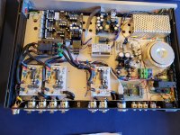
pre installation into the 2nd hand HK AVR housing...compact inner dimensions. i drilled additionally holes in the bottom plate.
heat sink will be more up if i use pcb holder to get away from the bottom plate.
have a nice evening
heat sink will be more up if i use pcb holder to get away from the bottom plate.
have a nice evening
Attachments


Are you talking about the phase shift of the amp output vs input?Hi X,
when is it critical for phase shift at the amp?
If I understand amp stability analysis correctly, we want to maintain a 45deg phase margin at the max operating frequency of the amp. See if the output shift is 135 deg or less (same as 45 deg margin of safety from 180deg). The FX8 was designed by Apex Audio and he is an experienced designer so I assume he took care of all of the stability margins in the initial design and I replaced the outputs with MOSFETs and it became the FH9. I have not performed a phase shift measurement myself. It would be interesting to see how it simulates in for phase in LTSpice.
Roughly looking at your Oscope shot, I would say that is a 45 deg shift. You have 90deg left of phase to go before bad things might happen. But having the output inductor parallel resistor Thiele circuit generally protects from load induced instability.
- Home
- Amplifiers
- Solid State
- FH9 XRK mod