Hi,
I'm just about two design my first serious attempt to build a 2-way speaker, all calculation are made but one; what the total impedance of the speaker will be.
I've decided to use a 8 ohm tweeter and a 8 ohm woofer. I'm using a 12dB/octave butterworht crossover and I'll reduce the tweeter about 4-6 dB using resistor. The speakers will be wired parallel.
Of coarse the impedance of the whole speaker will be 4 ohm, cause the elements are wired parallel I keep thinking. But somehow I doubt, don't know why. I've tried to find any information and done some complex calculation but gone nowhere. So please help me sleep at night and tell me if I'm right or if (I sometimes suspect) that I've missed something here. Does the crossover affect it or the reducing of the tweeter?
Sleeping well is a good thing!
🙄Speaker system impedance can be a tricky thing. If you are implementing a traditional 12db/octave passive crossover with two each 8 ohm nominally rated drivers, you will likely have what is considered an 8 ohm speaker.
System impedance usually is all over the place depending on the interaction of the crossover circuits as well as driver native impedance curves. I consider the lowest point in a driver's curve as the true impedance. Often drivers that are advertised as having an 8 ohms or higher impedance over the majority of their usable frequency range can have measured impedance's of 5-6 ohms. Most 8 ohm (ac) resistance drivers typically have 5-6 ohm (dc) resistance. The difference is the drivers reluctance, which is frequency dependent.
However, there are additional factors that can come together to lower parts of the electrical summation below 8 ohms. If one of your drivers has an impedance dip below 8 ohms, or if there is an interaction created by the combination of the high and low pass circuits and or the drivers reacting with the high and low pass circuits you can end up with portions of the impedance curve well below 8 ohms. Certain Zobel and traps applications can force portions of the system impedance down into the 2-6 ohm range.
Although the high and low pass circuits are parallel, the inductor on the low pass and the capacitor on the high pass isolate the two circuits. Also you have to account for series resistances of inductors and certain traps. These resistances ad to the system DC resistance and therefore can raise the system impedance.
I have designed two way speakers that exhibit impedance's ranging from 7 ohms to over 100 ohms! Most of the spectrum was between 8-12 ohms. However this same speaker is flat as a pancake in the frequency domain. You also have to look at phase relationships. Low impedance and large phase shifts occurring together can be a problem for many amplifiers.
If you could, tell us what exactly you are doing. What drivers and the basic crossover layout.
pyromaniac,
You can do it.
First, note that there are simple rules (algebraic equations) for finding the single overall impedance that results from having impedances in series (just add them) and from impedances in parallel (just add their reciprocals, e.g. 1/Z).
If you learn those rules, then more-complex networks of impedances can also be analyzed, by first breaking them down into pieces to which the simple rules apply and then combining those pieces with the rules, and so on, to eventually find the one resulting impedance expression for the whole network.
Impedance depends on frequency. But if you know the (extremely simple) algebraic expressions for the impedances of capacitors and inductors, in terms of frequency, and also know the basic impedance-combining rules that I mentioned above, then you can find the impedance expression for any practical complex RLC network and graph the impedance versus frequency, or plug in a frequency and calculate the impedance for any one frequency.
The only other trick that you might need or want to know is how real capacitors and inductors (and resistors) differ from ideal ones. It is simply that every real component actually has all three, capacitance, inductance, and resistance, but the two that are not what the component is named are much less evident than the main one it's supposed to be, and are called "parasitic" components or impedances.
So each real component can actually be "modeled" as a small network of series and/or parallel ideal components. But the same rules apply and you can still come up with one overall expression in terms of frequency, for any network of components, by using either ideal impedances to represent each of them or by using real components' equivalent-RLC-impedance-network models to represent each of them. Speaker drivers also have such impedance models.
You can do a google or wikipedia search for "series impedances equation", and "parallel impedances equation", and maybe "impedance tutorial". ("Tutorial" is like a magic word, for searching for something you want to learn about.)
If you then also looked up "voltage divider equation", then you should be able to analyze and design passive filters (low-pass, high-pass, and band-pass, for example).
Cheers,
Tom
Last edited:
The driver sections in a 'typical' crossover show a high impedance outside of their intended band, it is as if a tweeter is not even there throughout the bass region and vice-versa. Unless you measure, you can create unexpected results though if you do anything unconventional.
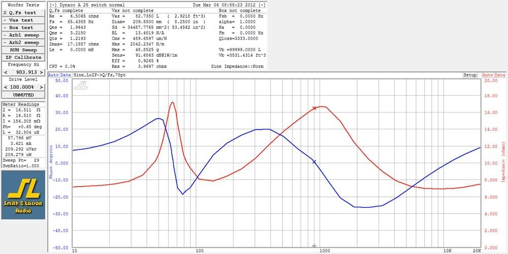
A picture is worth a 1000 words.
Here's an example of how impedance (red line) can vary with frequency. It's a measurement taken on the classic Dynaco A 25 (over 1 million made). In this case the impedance varies from about 7 to 17 ohms.
Here's an example of how impedance (red line) can vary with frequency. It's a measurement taken on the classic Dynaco A 25 (over 1 million made). In this case the impedance varies from about 7 to 17 ohms.
Last edited:
This is a good example of what the impedance would look like, and would be the first thing to look for.impedance (red line).....In this case the impedance varies from about 7 to 17 ohms.
I am reluctant to muddy up the thread with technicalities, but the impedance is in fact both curves (otherwise it would be called resistance). They are inseperable in practice and as John Bsuch pointed out, extremes of either are undesirable.
Of coarse the impedance of the whole speaker will be 4 ohm, cause the elements are wired parallel I keep thinking. But somehow I doubt, don't know why.
The idea of a crossover network is to isolate each of the drivers from the other electrically. Following this, the usual rules of series/parallel elements don't apply.
I'll reduce the tweeter about 4-6 dB using resistor. The speakers will be wired parallel.
Better use an L-pad. This consists of two resistors, and keeps the impedance seen by the crossover the same as with no attenuation. A different impedance means a different crossover point when you use the same crossover components.
- Status
- Not open for further replies.
- Home
- Loudspeakers
- Multi-Way
- Final impedance of 2-way speaker (am I stupid or not?)