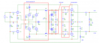
So, in my typical style I've decided to run before I can walk and design a (probably overcomplicated) differential output front end for a bridged amplifier (no idea what the back end will be, that'll come later). It seems alright-ish in the sim to my very inexperienced eyes, but hopefully you fine folk here can tell me how it'll explode if I ever build it.

(X1+X2) and (X3+X4) are ECF80s, with the triodes being used as an input buffer and the pentodes as a constant-ish current load for the shunt cascode. I realise I could probably get away without the buffer but I have the tubes already, the pentodes seem to work well as a CCS and the triodes were going spare.
(X5+X6) and (X7+X8) are ECC84s, paralleled for a higher current swing.


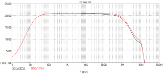
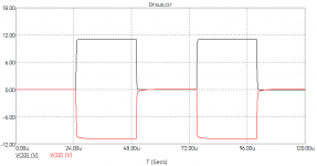
I was looking for enough gain to drive 30 watts into an 8 ohm load, and I've overshot a little but that's easy to dial back. The response to a 20khz square wave looks fairly nice. Is the slight gain mismatch (V32 is - out and V33 is + out) something I should worry about? I tried to make the amp stable while leaving the step response as good as possible, but should I roll off the higher frequencies more?

Running about 36dB of feedback, I had a fair old problem with instability but I think I've managed to rein it in. At the moment the gain margin is 11db with a phase margin of 54 degrees.
Hopefully you can let me know whether this is a viable design, or whether it's way overcomplicated. Any input is welcome, I'm a complete newbie.
Many thanks
Boulder

(X1+X2) and (X3+X4) are ECF80s, with the triodes being used as an input buffer and the pentodes as a constant-ish current load for the shunt cascode. I realise I could probably get away without the buffer but I have the tubes already, the pentodes seem to work well as a CCS and the triodes were going spare.
(X5+X6) and (X7+X8) are ECC84s, paralleled for a higher current swing.


I was looking for enough gain to drive 30 watts into an 8 ohm load, and I've overshot a little but that's easy to dial back. The response to a 20khz square wave looks fairly nice. Is the slight gain mismatch (V32 is - out and V33 is + out) something I should worry about? I tried to make the amp stable while leaving the step response as good as possible, but should I roll off the higher frequencies more?

Running about 36dB of feedback, I had a fair old problem with instability but I think I've managed to rein it in. At the moment the gain margin is 11db with a phase margin of 54 degrees.
Hopefully you can let me know whether this is a viable design, or whether it's way overcomplicated. Any input is welcome, I'm a complete newbie.
Many thanks
Boulder
Last edited:
i would say the reality of stability issues will be much more serious then your sim results suggest (an idealized model not taking account of build factors), trying to apply feedback over so many stages is asking for trouble.
Shoog
Shoog
Well, it is, for certain for me, a somewhat complicated design to get to the bottom. 😱
Current sources I1+I2 >I3. Where does that 10mA difference go?
Ah, I see, the difference goes into those PNP's
Current sources I1+I2 >I3. Where does that 10mA difference go?
Ah, I see, the difference goes into those PNP's
Last edited:
RC paralleled networks at the final grids (Cathode followers) are useless because they don't have any load, only the internal capacitance (small in a CF).
Those phase advance nets looks to be matter for complications.
Those phase advance nets looks to be matter for complications.
So, in my typical style I've decided to run before I can walk and design a (probably overcomplicated) differential output front end for a bridged amplifier (no idea what the back end will be, that'll come later). It seems alright-ish in the sim to my very inexperienced eyes, but hopefully you fine folk here can tell me how it'll explode if I ever build it.
Well I had over the baton of complicaté lol. I thought I was bad.
From my limited 'experience' the model will end up being a lot more complicated in physical reality - especially when R&Ding it. Expect tuning pots and other such things to take up real estate.
I can't remember but I didn't see a fuse in that 😀
Also possibly worth just putting a THD or Fourier.. although simulations will not help with the real distortion they do help get a feel/hit the side of the barn.
Last edited:
Oh - check the heater-cathode on that. the ECF80s data sheet states positive 100V or negative 100Vdc component out of the quoted 200V. I see you have -175 to 175V so worth checking.
Also have you sim'd the startup/shutdown?
Also have you sim'd the startup/shutdown?
Looks like a lot of stuff just for 'alrightish'... A simple phase inverter and a couple of cathode followers would probably perform better and be less likely to fail or bankrupt you! Tubecad's latest blog is exactly on this subject (you can always add a gain stage up front):It seems alright-ish in the sim
Unity-Gain Phase Splitters
Last edited:
Oh - check the heater-cathode on that. the ECF80s data sheet states positive 100V or negative 100Vdc component out of the quoted 200V. I see you have -175 to 175V so worth checking.
Also have you sim'd the startup/shutdown?
The reality is that the ECF80 is significantly more tolerant than the datasheet suggests.
Shoog
The reality is that the ECF80 is significantly more tolerant than the datasheet suggests.
I've learnt this year, unlike mosfets, valves 'maximums' are more sort of like sortta-rough-guestimate. B+ voltages too. I'll shut up and sit that the back of the bus 😀
...Hopefully you can let me know whether this is a viable design...
The correct way to design a circut (or to design anything in general) is to start with a requirements analysis. What are the requirements? What do you want this thing to do?
Once you state your requirements in detail, you will likely get very helpful input.
If your only requirement (as stated) is to provide a pair of complementary outputs to drive a power stage, then this is a vastly and unnecessarily complex circuit.
Well, it is, for certain for me, a somewhat complicated design to get to the bottom. 😱
Current sources I1+I2 >I3. Where does that 10mA difference go?
Ah, I see, the difference goes into those PNP's
It's a shunt cascode, explained a bit more here (I believe the original thread on this forum) and here (Bartola)
Looks like a lot of stuff just for 'alrightish'... A simple phase inverter and a couple of cathode followers would probably perform better and be less likely to fail or bankrupt you! Tubecad's latest blog is exactly on this subject (you can always add a gain stage up front):
Unity-Gain Phase Splitters
You have a good point, and I'm fairly sure there's a tubecad article on pretty much anything you could want to build. I'm stubborn though, so if I can get this topology working, I will. I'll definitely try to simplify it though.
- Home
- Amplifiers
- Tubes / Valves
- First amp design - feedback needed