Is there any calculator or formula for reverse calculating results of “third-order” crossover such as crossover frequency and Q-factor from component values?
In second-order crossover, there are two formulas which are resonance (f = 1/(2 x Pi x sqrt(L x C)) and Q-factor (Q = sqrt(R^2 x L/C)) formulas so that we can definitely reverse calculating crossover frequency and Q from any given L and C values.
How about third-order crossovers?
Please do not suggest me to go using Xsim or VituixCAD because I’d like to know the simple and quick methods to approximately estimate the circuit.
Unfortunately, sometimes I cannot access to my computer, but only iPad or calculator.in their library
In fact, I should tell my exact question because it may help readers to understand easier.
I’m planning to build a switchable mode between second- and third-order high-pass filter for my tweeters. My current high-pass is originally second-order with a series 6.8uF capacitor and a shunt 0.2mH inductor connected to a 3.2 Ohms tweeter. It has a resistor in series with the tweeter with a switch paralleled to it for enabling bypassing or not. I think to replace the resistor with a capacitor so that I could switch modes between second- or third-order instead. But I’ve never experienced with third-order before. So I don’t know which value of the second capacitor I should use.
I know XSim or VituixCAD can help, but I just visited here before seeing them if there’s what I’m looking for, the formulas.
This, please.keep the first two and just add a third
I'd like to retain the original characteristic when using 2nd-order mode and a mild cut in 3rd-order mode.
Here is the current schematic of my speakers.
On the right is a three-position switch. The top position is no attenuation. The middle position is a mild cut by a 0.75R with second-order mode. The bottom position is the mild cut with third-order mode.

On the right is a three-position switch. The top position is no attenuation. The middle position is a mild cut by a 0.75R with second-order mode. The bottom position is the mild cut with third-order mode.
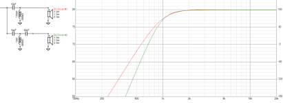
Sesbe is correct, that is a resistor, not a capacitor. If you trace out the schematic with each switch position you will discover there are just three levels of attenuation of the tweeter level. The adjustments will not change the slope of the XO, just the level and a modest adjustment of the crossover frequency. If you want to change the slope of the XO by changing just on component you will need to do some rewiring not just replace the resistor with a capacitor. I did two simulations for you, VituixCAD doesn't have a switch so I just used a resistor and open and short it. I don't think this will work very well, switching the cap in and out does change the slope, but also switches the XO frequency from 3200 hz to 2500 hz which would make a mess with the midrange. Also the 2 mH shunt inductor on the the tweeter in the schematic could be a mistake because it must be much a lower value.


Perhaps presscot intends to place the capacitor there to change to third order. In that case the indictor would have to move to a position between the capacitors.
- Home
- Loudspeakers
- Multi-Way
- First time with a question on Third-order crossover
