Hi
I am not sure if this is the right place to ask this. Feel free to point me to the best forum category. Electrolytic capacitors are mainly used because they are cheaper and smaller and they can hold a much higher capacitance.
My amplifier uses 3x 220uF 450V capacitors for the power supply. I am looking to do some upgrades and I never looked at foil capacitors for those values because I thought they don't exist. However, they do actually exist.
Would there by any benefit in using foil capacitors over electrolytics for power supplies and cathode bypass? Provided there is enough space and they have the necessary capacitance and voltage.
I'd love to hear your opinion
Absolutely no advantage with the exception of a CLC type 5U4 or GZ34 rectifier. The cathode of the rectifier feeds the first capacitor known as the tank capacitor, usually between 4 and 8uF oil type. This then feeds the second capacitor through the choke. A 47uF electrolytic will smooth out the DC power. Any lumps or bumps are smoothed out by the reactance between the choke and feed capacitor.
Otherwise with silicon diodes, use what you like in electrolytic form. Bearing in mind the current draw from the transformer trying to fill up the tank capacitor. I have seen many transformer fail due to the value being too large.
Otherwise with silicon diodes, use what you like in electrolytic form. Bearing in mind the current draw from the transformer trying to fill up the tank capacitor. I have seen many transformer fail due to the value being too large.
Yes, less hum/ESR, higher ripple current, and no degradation with use.
To limit the peaks of the input current spikes, use a small resistor before the first capacitor.
You may not have enough room for the much larger film equivalents, though.
https://www.ecicaps.com
To limit the peaks of the input current spikes, use a small resistor before the first capacitor.
You may not have enough room for the much larger film equivalents, though.
https://www.ecicaps.com

Interesting. I've got a World Audio Designs WAD6550 push pull kit. It has 5U4 rectifiers and CLC filtering (50uF/2.5H/50uF). The kit came with 100uF electrolytic caps used in series with balancing resisters. I managed to replace those caps with 47uF oil type caps. Foolishly, I replaced the coupling caps with PIO's at the same time, so it is hard to say what the sonic difference was. (I replaced the PIO coupling caps with plastic caps later, which I actually found to prefer.)Absolutely no advantage with the exception of a CLC type 5U4 or GZ34 rectifier. The cathode of the rectifier feeds the first capacitor known as the tank capacitor, usually between 4 and 8uF oil type. This then feeds the second capacitor through the choke. A 47uF electrolytic will smooth out the DC power. Any lumps or bumps are smoothed out by the reactance between the choke and feed capacitor....
What value too large?Absolutely no advantage with the exception of a CLC type 5U4 or GZ34 rectifier. The cathode of the rectifier feeds the first capacitor known as the tank capacitor, usually between 4 and 8uF oil type. This then feeds the second capacitor through the choke. A 47uF electrolytic will smooth out the DC power. Any lumps or bumps are smoothed out by the reactance between the choke and feed capacitor.
Otherwise with silicon diodes, use what you like in electrolytic form. Bearing in mind the current draw from the transformer trying to fill up the tank capacitor. I have seen many transformer fail due to the value being too large.
In our SE builds we found that using polys in the power supply made a huge improvement. Since then we have not done any with elcos.
dave
dave
Last edited:
Interesting, thanks for sharing.In our SE builds we found that using polys in the power supply made a huge improvement. Since then we have not done any with elcos.
dave
What capacitance did they have or do you typically use (assuming that matters)?
Any brand/model you can recommend?
Cheers
We used the cheap Solens.
In an SE amp the last cap in the power supply is in the signal path.
dave
In an SE amp the last cap in the power supply is in the signal path.
dave
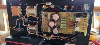
I passed by a capacitor bank in a three-phase 150 kV system last Sunday. It's completely irrelevant, but it is a nice picture of large non-electrolytic capacitors.

We used the cheap Solens.
nice thanks,
would you even use polys for capacitors as large as 220uF if there is enough room and cost is not a problem?
just trying to get to the bottom of it
Yes. Allen Wright’s PP amp uses 4 (at least that big), they are in the towers.

Worth noting that you do not want a big cap right after the rectifier.
dave
Worth noting that you do not want a big cap right after the rectifier.
dave
Yes. Allen Wright’s PP amp uses 4 (at least that big), they are in the towers.
Ah nice thanks for all your answers, I learned quite a bit - I hope others did aswell.
I have one last question if you don't mind. Is it worth spending a bit more for a higer-end poly capacitor for the RC Filter? Would the difference be negligible between, let's say a Solen PPE FastCap and a ClarityCap CSA which costs 3x as much?
I can’t say. If they make a difference in a coupling cap then likely the last cap in an SE should do the same, in a PP the jury is out.
dave
dave
I know that different brands of electrolytic power supply caps can make a big difference in the sound of a push pull amp.
I use poly caps in my SE amp too. They seem to lower the noise floor and have lower ESR that gives faster power delivery and tighter bass. I found Apex Jr on the auction site has cheap 75uf 600v poly caps for like $5 each that work really well. If you use a tube rectifier you need sub 50uf cap right after the tube. They are bigger than the electrolytic caps but they end up being more convenient as you only need one as opposed to two in series for voltages over 450v like most common electrolytics. They last forever as a bonus. I see no down side.
What makes that only with "a CLC type 5U4 or GZ34 rectifier" there is an advantage in using a capacitor other than an electrolytic, while in every other situation there is "absolutely no advantage"? What is so special about the 5U4 or GZ34 in combination with CLC that this would be true?Absolutely no advantage with the exception of a CLC type 5U4 or GZ34 rectifier. The cathode of the rectifier feeds the first capacitor known as the tank capacitor, usually between 4 and 8uF oil type. This then feeds the second capacitor through the choke. A 47uF electrolytic will smooth out the DC power. Any lumps or bumps are smoothed out by the reactance between the choke and feed capacitor.
Otherwise with silicon diodes, use what you like in electrolytic form. Bearing in mind the current draw from the transformer trying to fill up the tank capacitor. I have seen many transformer fail due to the value being too large.
Nothing, that was just an example. EZ81, 5Y3 etc etc are similar but the GZ34 can stand a higher capacitance on the cathode than say a 5Y3 or GZ37 or U54 as the latter can only use a 4uF tank capacitor. Have a look at the valve data sheets.What makes that only with "a CLC type 5U4 or GZ34 rectifier" there is an advantage in using a capacitor other than an electrolytic, while in every other situation there is "absolutely no advantage"? What is so special about the 5U4 or GZ34 in combination with CLC that this would be true?
OK, now you are changing your statement from "Absolutely no advantage with the exception of a CLC type 5U4 or GZ34 rectifier." to something like: "Absolutely no advantage with the exception of many exceptions".
This thread is not about the value of the (first) capacitor in power supplies but about the question if foil capacitors have benefits over electrolytic capacitors in certain applications, like power supplies. So why should I have a look at the valve datasheets? I never saw a datasheet for a valve rectifier that stated something about possible (dis)advantages of certain types of capacitors.
This thread is not about the value of the (first) capacitor in power supplies but about the question if foil capacitors have benefits over electrolytic capacitors in certain applications, like power supplies. So why should I have a look at the valve datasheets? I never saw a datasheet for a valve rectifier that stated something about possible (dis)advantages of certain types of capacitors.
No HiFi designer will ever put the most expensive capacitors and components in general a circuit tbh. Find me one amplifier that stock uses OCC copper wires $70 capacitors, Audio Note non-magnetic silver Nobium resistors which cost $40 each. Or 4oz copper PCB, heck you can even go higher but then you pay $500 for a PCB.If they are magical, as many seem to thing, why didn't Quad, Leak and many more renown HiFi designer incorporate them in their designs I wonder.
A good quality electrolytic or two and decent mains borne interference reduction, is all that is required.
Also reasonably priced high capacitance foil capacitors is a new thing. A 220uF 450V electrolytic costs $10 a foil will be $60.
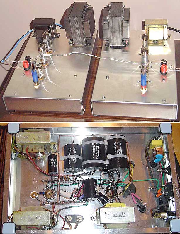
My amplifier has a rectifier and it doesn't have a tank capacitor.If you use a tube rectifier you need sub 50uf cap right after the tube.
It has 2x 22uF 500V RC filter
2x 0.22uf 450V signal
2x 220uF 16V cathode bypass
3x 220uF 450V power supply.
It has no capacitors after the rectifier. The 3 PSU caps are directly in front.
Attachments
- Home
- Amplifiers
- Power Supplies
- Foil vs electrolytic capacitors for tube amplifier power supplies