Over this weekend, I started collecting parts for a Frankentracer build. In the spirit of Michael Rothacher's original concept, I scrounged up all the electronic parts from my parts graveyard and existing inventory. I only bought a carriage bolt to mount my toroid transformer and rubber feet for the base. So it is truly a Frankenstein's monster.
I built most of it yesterday (Halloween, very auspicious) and finished it off today. I've tested the voltages and all is good, although I haven't tested a SIT yet, so technically Frankentracer has not yet come to life. I think once the light bulb glows, Frankentracer will have taken its first breath.
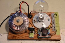
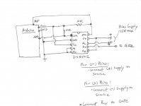
I used an isolation toroid transformer with centre tapped secondary for power. One half of the secondary (60VAC) feeds into an old bridge rectifier to provide positive and negative voltage outputs. Frankentracer is set up to be configurable with jumpers for either positive or negative Vds and Vgs so I can test both P an N type SITs.
I built most of it yesterday (Halloween, very auspicious) and finished it off today. I've tested the voltages and all is good, although I haven't tested a SIT yet, so technically Frankentracer has not yet come to life. I think once the light bulb glows, Frankentracer will have taken its first breath.
I used an isolation toroid transformer with centre tapped secondary for power. One half of the secondary (60VAC) feeds into an old bridge rectifier to provide positive and negative voltage outputs. Frankentracer is set up to be configurable with jumpers for either positive or negative Vds and Vgs so I can test both P an N type SITs.
Attachments

Frankentracer is alive!
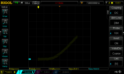
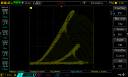
I connected a Russian 2P926B SIT to the Frankentracer today and fired it up. I was very cautious, so it was many Vds and Vgs baby steps before I finally got the SIT to conduct. Well, first I had to figure out how to display XY plots of my Rigol DS1054. Then I was twiddling the variac and the Vgs knobs while inspecting the various voltmeters. No joy. Finally, I got wise and just used the scope in two channel mode to monitor Vds and Iq (voltage across the 1 ohm source resistor) while adjusting the two voltages. When I finally got current flow, I then switched to XY mode and played with Vgs. So, much time was spent before the line emerged from the weeds and changed to a curve.
I forgot to write down the Vgs, but I think it was around -1.2V. Vds was 25.6V with I at 164mA.
Now I can trace some of my SITs and work on another amp design.
Attachments
Frankentracer Gets a Brain and Other Body Parts
Since creating Frankentracer, I really haven't used it because it needed many steps to produce a set of curves for a device. It required twisting Frankentracer's gate potentiometer to various positions and then capturing the Voltage-Current plot for that Vgs. After all the curves are acquired, then the screen captured images need to be overlayed to produce a composite image. At least, that's what I figured needed to be done.
Now, I'm kinda lazy, so I went about doing other more interesting things while contemplating how to make Frankentracer reduce my work load. I know there are various methods of creating a curve tracer, but I didn't want to design such a full-blown device. I just wanted to automate Frankentracer a little bit.
A few weeks ago, on my travels through the 'net, I stumbled upon a digital potentiometer integrated circuit. Bingo! Just what Frankentracer needed. It could replace the manually adjusted (by me) potentiometer and Frankentracer would make the stepped gate voltages by itself. That way, the oscilloscope would capture all the curves in one shot. But for that to happen, Frankentracer needed a brain.
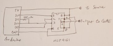
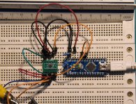
Luckily, I have a few spare brains (Arduinos) in my graveyard (parts bin) that I could give to Frankentracer. For the digital potentiometer (MCP4161), I added a couple of pieces to my last Digikey order. The courier brought the parts the other day, so I programmed the Arduino and attached the potentiometer yesterday. Now, Frankentracer could turn the potentiometer knob (figuratively) for me.
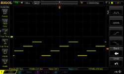
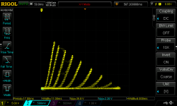
My test program and setup is not fine-tuned, but it demonstrates that the system can do what I wanted.
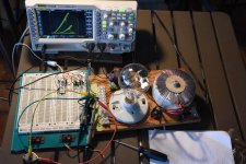
The attached images include the FrankenDuinoTracer in action, the Arduino/digital pot schematic, the stepped negative voltage pot output, and the curves for a 2P926B SIT.
The Arduino program:
//
// FrankenDuino with
// digital potentiometer
//
#include <MCP4131.h>
int calc4161WiperValue(float VW, float VA, float VB);
const int chipSelect = 10;
// Create MCP4131 object nominating digital pin used for Chip Select
MCP4131 Potentiometer(chipSelect);
void setup() {
// Reset wiper position to 0 Ohms
wiperValue = 0;
Potentiometer.writeWiper(wiperValue);
}
void loop() {
int wiper;
float v;
// my Arduino's 5V out measured 4.6V
// for ground = 0V, output to gate will increase from 2.5V
// for ground = +4.6V, output to gate will decrease (become more negative) from approx -2.5V
//
for (v = 2.5; v < 4.5; v += 0.5){
wiper = calc4161WiperValue(v, 4.6, 0.0);
Potentiometer.writeWiper(wiper);
}
}
Since creating Frankentracer, I really haven't used it because it needed many steps to produce a set of curves for a device. It required twisting Frankentracer's gate potentiometer to various positions and then capturing the Voltage-Current plot for that Vgs. After all the curves are acquired, then the screen captured images need to be overlayed to produce a composite image. At least, that's what I figured needed to be done.
Now, I'm kinda lazy, so I went about doing other more interesting things while contemplating how to make Frankentracer reduce my work load. I know there are various methods of creating a curve tracer, but I didn't want to design such a full-blown device. I just wanted to automate Frankentracer a little bit.
A few weeks ago, on my travels through the 'net, I stumbled upon a digital potentiometer integrated circuit. Bingo! Just what Frankentracer needed. It could replace the manually adjusted (by me) potentiometer and Frankentracer would make the stepped gate voltages by itself. That way, the oscilloscope would capture all the curves in one shot. But for that to happen, Frankentracer needed a brain.
Luckily, I have a few spare brains (Arduinos) in my graveyard (parts bin) that I could give to Frankentracer. For the digital potentiometer (MCP4161), I added a couple of pieces to my last Digikey order. The courier brought the parts the other day, so I programmed the Arduino and attached the potentiometer yesterday. Now, Frankentracer could turn the potentiometer knob (figuratively) for me.
My test program and setup is not fine-tuned, but it demonstrates that the system can do what I wanted.
The attached images include the FrankenDuinoTracer in action, the Arduino/digital pot schematic, the stepped negative voltage pot output, and the curves for a 2P926B SIT.
The Arduino program:
//
// FrankenDuino with
// digital potentiometer
//
#include <MCP4131.h>
int calc4161WiperValue(float VW, float VA, float VB);
const int chipSelect = 10;
// Create MCP4131 object nominating digital pin used for Chip Select
MCP4131 Potentiometer(chipSelect);
void setup() {
// Reset wiper position to 0 Ohms
wiperValue = 0;
Potentiometer.writeWiper(wiperValue);
}
void loop() {
int wiper;
float v;
// my Arduino's 5V out measured 4.6V
// for ground = 0V, output to gate will increase from 2.5V
// for ground = +4.6V, output to gate will decrease (become more negative) from approx -2.5V
//
for (v = 2.5; v < 4.5; v += 0.5){
wiper = calc4161WiperValue(v, 4.6, 0.0);
Potentiometer.writeWiper(wiper);
}
}
Attachments

Oh, just realized that I missed showing a function needed for the Arduino program:
//
// VW = voltage at wiper (pin 6)
// VA = voltage at A (pin 5)
// VB = voltage at B (pin 7)
//
int calc4161WiperValue(float VW, float VA, float VB)
{
// 1 wiper step = (VA - VB) / 256;
double wiperStep = (VA - VB) / 256.0;
return VW / wiperStep;
}
//
// VW = voltage at wiper (pin 6)
// VA = voltage at A (pin 5)
// VB = voltage at B (pin 7)
//
int calc4161WiperValue(float VW, float VA, float VB)
{
// 1 wiper step = (VA - VB) / 256;
double wiperStep = (VA - VB) / 256.0;
return VW / wiperStep;
}
I made some improvements to the Frankentracer-Arduino mashup. The digital potentiometer that I used to control the bias voltage, MCP4161, is only rated for 5 volts across the potentiometer. It is possible to have higher voltage bias supplies by adding resistors in series with the digital pot but it is pain and the operating range of the bias output is still limited to 5V. There is a high voltage version of the MCP4161 which can handle 35V across the pot, but it is out of stock everywhere and will be for a while.
Fortunately, there is an alternative which is available for purchase - the DS3502 digital pot. It doesn't quite have the same high voltage handling capability, but it is rated for 15V, which is good enough for me.
It is a surface mount device (MSOP-10), though, so that presented a challenge for me. I've never soldered a SMD device before, so I was a bit leery about using it. One alternative is to buy an Adafruit breakout board with the DS3502 already soldered in place. But, it costs about $8 compared to less than $3 (Canadian) for the IC. In reality, it's not a bad deal but my time is cheap, and I'm cheap. So, it presented an opportunity to try something new.
Luckily, I was getting ready to order some PC boards for a different project so I decided to make my own MSOP-10 breakout boards. It's a good thing that I learned how to use KiCad. In the end, adding 5 breakout PCBs to the order only cost me an extra $2.
So, long story short, I got the improved Frankentracer working with this new Arduino/DS3502 bias supply. I adjusted the timing loop in the Arduino bias program to improve the XY plot on my Rigol scope, and also fiddled with its memory parameters to clean up the XY plot some more.
Now, I can hook up a 15V power supply to the Arduino controlled bias system and just change the program parameters to produce the desired staircase bias voltages.
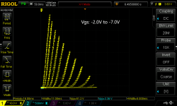
The plot shown is for a 2SK182ES with Vgs starting a -2.0V and incrementing by 0.5V. Horizontal scale is 5V; vertical is 0.5V (0.5A).
Fortunately, there is an alternative which is available for purchase - the DS3502 digital pot. It doesn't quite have the same high voltage handling capability, but it is rated for 15V, which is good enough for me.
It is a surface mount device (MSOP-10), though, so that presented a challenge for me. I've never soldered a SMD device before, so I was a bit leery about using it. One alternative is to buy an Adafruit breakout board with the DS3502 already soldered in place. But, it costs about $8 compared to less than $3 (Canadian) for the IC. In reality, it's not a bad deal but my time is cheap, and I'm cheap. So, it presented an opportunity to try something new.
Luckily, I was getting ready to order some PC boards for a different project so I decided to make my own MSOP-10 breakout boards. It's a good thing that I learned how to use KiCad. In the end, adding 5 breakout PCBs to the order only cost me an extra $2.
So, long story short, I got the improved Frankentracer working with this new Arduino/DS3502 bias supply. I adjusted the timing loop in the Arduino bias program to improve the XY plot on my Rigol scope, and also fiddled with its memory parameters to clean up the XY plot some more.
Now, I can hook up a 15V power supply to the Arduino controlled bias system and just change the program parameters to produce the desired staircase bias voltages.
The plot shown is for a 2SK182ES with Vgs starting a -2.0V and incrementing by 0.5V. Horizontal scale is 5V; vertical is 0.5V (0.5A).
Attachments
The Arduino automatically steps the bias Vgs so all the curves are displayed simultaneously. To capture the image, I just insert an USB drive into the Rigol and press the Print button. No need to capture each Vgs curve separately.
I'll add the schematic and Arduino program tomorrow.
I'll add the schematic and Arduino program tomorrow.
Here is the Arduino program that generates the bias staircase voltage waveform:
//
#include <Adafruit_DS3502.h>
Adafruit_DS3502 ds3502 = Adafruit_DS3502();
/*
*
* Bias connections:
*
* DS3502 RH to Bias supply +
* DS3502 RL to Bias supply GND
*
* DS3502 RW to gate
* Negative Bias - connect DS3502 RH to source
* Positive Bias - connect DS3502 RL to source
*
*/
// set BIAS_SUPPLY_VOLTAGE as positive value
// cannot be greater than DS3502 limit of 15V
#define BIAS_SUPPLY_VOLTAGE 10.0
// set BiasPolarity to -1 for negative bias, 1 for positive bias
int BiasPolarity = -1;
int calc4161WiperValue(float VW, float VH);
void setup() {
Serial.begin(115200);
// Wait until serial port is opened
while (!Serial) { delay(1); }
Serial.println("Adafruit DS3502 Test");
if (!ds3502.begin()) {
Serial.println("Couldn't find DS3502 chip");
while (1);
}
Serial.println("Found DS3502 chip");
}
void loop() {
int wiper;
float v;
// generate bias staircase voltage
// set the bias voltage limits (absolute value) and step size
//
// following generates staircase voltage output from 2V to 7V at 0.5V increments
for (v = 2; v <= 7.0; v += 0.5){ // v must be <= BIAS_SUPPLY_VOLTAGE
if (BiasPolarity == -1) {
// RW will be relative to RH
wiper = calc4161WiperValue(BIAS_SUPPLY_VOLTAGE - v, BIAS_SUPPLY_VOLTAGE);
}
else {
// RW will be relative to RL
wiper = calc4161WiperValue(v, BIAS_SUPPLY_VOLTAGE);
}
ds3502.setWiper(wiper);
delay(30); // experiment with delay value for best XY plot
}
}
//
// VW = voltage at wiper RW (pin 7)
// VH = voltage at RHigh (pin 6)
// VL = voltage at RLow (pin 8) = 0.0
//
int calc4161WiperValue(float VW, float VH)
{
// 1 wiper step = VH / 127;
double wiperStep = VH / 127.0;
return VW / wiperStep;
}
// end of program
Presently, values are set in the program for:
The program is uploaded to the Arduino and it will run according to the values set. To change the bias waveform, the program values must be edited and re-uploaded to the Arduino. However, the Arduino will retain the program when it is powered down.
For occasional use, reprogramming is not too much of a hassle. For more frequent use, it would make sense to add a few switches, potentiometers, and resistors to the circuit and modify the program so the bias parameters can be changed via the switches and pots. This way, the Arduino would not need to be reprogrammed using an external computer every time new bias conditions are desired. It wouldn't be difficult to do and the result would be a simple, cheap curve tracer with high voltage/current capabilities.
//
#include <Adafruit_DS3502.h>
Adafruit_DS3502 ds3502 = Adafruit_DS3502();
/*
*
* Bias connections:
*
* DS3502 RH to Bias supply +
* DS3502 RL to Bias supply GND
*
* DS3502 RW to gate
* Negative Bias - connect DS3502 RH to source
* Positive Bias - connect DS3502 RL to source
*
*/
// set BIAS_SUPPLY_VOLTAGE as positive value
// cannot be greater than DS3502 limit of 15V
#define BIAS_SUPPLY_VOLTAGE 10.0
// set BiasPolarity to -1 for negative bias, 1 for positive bias
int BiasPolarity = -1;
int calc4161WiperValue(float VW, float VH);
void setup() {
Serial.begin(115200);
// Wait until serial port is opened
while (!Serial) { delay(1); }
Serial.println("Adafruit DS3502 Test");
if (!ds3502.begin()) {
Serial.println("Couldn't find DS3502 chip");
while (1);
}
Serial.println("Found DS3502 chip");
}
void loop() {
int wiper;
float v;
// generate bias staircase voltage
// set the bias voltage limits (absolute value) and step size
//
// following generates staircase voltage output from 2V to 7V at 0.5V increments
for (v = 2; v <= 7.0; v += 0.5){ // v must be <= BIAS_SUPPLY_VOLTAGE
if (BiasPolarity == -1) {
// RW will be relative to RH
wiper = calc4161WiperValue(BIAS_SUPPLY_VOLTAGE - v, BIAS_SUPPLY_VOLTAGE);
}
else {
// RW will be relative to RL
wiper = calc4161WiperValue(v, BIAS_SUPPLY_VOLTAGE);
}
ds3502.setWiper(wiper);
delay(30); // experiment with delay value for best XY plot
}
}
//
// VW = voltage at wiper RW (pin 7)
// VH = voltage at RHigh (pin 6)
// VL = voltage at RLow (pin 8) = 0.0
//
int calc4161WiperValue(float VW, float VH)
{
// 1 wiper step = VH / 127;
double wiperStep = VH / 127.0;
return VW / wiperStep;
}
// end of program
Presently, values are set in the program for:
- voltage of bias supply attached to the digital pot
- whether the bias is to be negative or positive
- the low and high limits of the output bias voltage
- the voltage increment for stepping the bias waveform
The program is uploaded to the Arduino and it will run according to the values set. To change the bias waveform, the program values must be edited and re-uploaded to the Arduino. However, the Arduino will retain the program when it is powered down.
For occasional use, reprogramming is not too much of a hassle. For more frequent use, it would make sense to add a few switches, potentiometers, and resistors to the circuit and modify the program so the bias parameters can be changed via the switches and pots. This way, the Arduino would not need to be reprogrammed using an external computer every time new bias conditions are desired. It wouldn't be difficult to do and the result would be a simple, cheap curve tracer with high voltage/current capabilities.
Attachments
Thanks!
Really, I must give credit to Michael for his idea of using rectified AC for the Vds waveform. It is a simple and cheap method for creating a high voltage/current, almost triangular wave. I just wanted to make it easier to produce a set of curves.
I've since added a potentiometer to change the frequency of the staircase Vgs waveform in real time. This allows the user to vary the frequency so it synchronizes with the Vds waveform for the best XY plot. The Vgs frequency is dependent on the Arduino operating speed and the number of steps in the Vgs waveform, so this adjustment can be used to optimize the XY plot. The attached XY plot shows Vds of over 50V with current over 3A. The effects of changing the Vgs frequency are noticeable.
The next step is to add a LCD screen and some more pots and switches to allow independent operation without an attached computer. This will allow changing the stepped Vgs waveform without reprogramming. The plan is to make a PCB for this.
Attachments
I have a Rigol scope so creating a JPG file on a USB memory stick is easy. Just insert a memory stick into the scope's USB port and press the Print button. That is how I get the plots to view on my PC. There are ways of capturing the data with the Rigol scope but I haven't tried that.
I do the same. I have tried exporting data from Rigol. It was one curve at a time and I couldn’t find a systematic way of eliminating the fuzziness and get the raw data into a usable form. I ended up having to do a curve fit for each line and then regenerate the curve from the fit. So I gave up and besides, the screenshot method gives the info you need for design purposes.
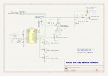
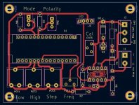
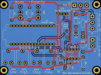
I've been working on a PCB for this Arduino controlled Frankentracer bias supply. It's mostly done. I'm going to order some parts so I can breadboard the various subcircuits, write some software, and test the functions.
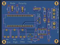
The circuit and software are fairly straight forward. A LCD display is connected to the Arduino Nano for user feedback, and switches and potentiometers are used to set the program parameters.
There are two modes: Set and Run. In Set mode, the bias output polarity, the bias low voltage, high voltage, and voltage step are set. A toggle switch changes between logic 1 and 0 at a digital input port to determine polarity. Potentiometers are used as voltage dividers to vary the Vcc voltage input to Analog Digital Converter ports to set the bias step waveform parameters. Run mode outputs the stepped waveform. The Set/Run mode is also determined by logic level at a digital input port.
During Run mode, an additional pot controlling voltage to an ADC input is used to vary the stepped waveform frequency. This is used to synchronize the bias waveform with the Vds waveform to minimize noise in the XY oscilloscope plot.
The voltage input to the circuit is polarity protected and limited to about 14V with zener and LED diodes. The DS3502 digital potentiometer is good for 15V. The resulting input voltage is scaled with a voltage dividing potentiometer and is applied to an Arduino ADC port so the voltage to the DS3502 potentiometer can be measured to calibrate the potentiometer output. The Arduino ports can only handle 5V, so the scaling is needed to handle bias voltages greater than 5V.
With the Lunar New Year celebrations happening, the circuit boards may take a few weeks. This will leave me time to finalize and test everything at a leisurely pace. Actually, I need to work on my SIT amp project.
Attachments
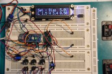
Over the last week, I've managed to put together a functioning prototype. I got some parts from DigiKey, wrote some software, and put it all together for testing. It is all complete except for the voltage input polarity and overvoltage protection circuit. For testing, I am using the 5V output from the Arduino Nano as the input bias supply so I didn't need to worry about input voltage issues.
After some minor circuit and software modifications, the Arduino interface worked as planned. I will finalized the circuit board and place an order in the next few days.
The LCD display is a DFRobot product. It shares the I2C data lines with the DS3502 digital potentiometer. There are other I2C LCD displays, but I chose this one as it is available from DigiKey, so I didn't have to pay extra postage or face a long wait to receive it.
As an aside, I'm impressed with the service from DigiKey. I placed an order in the early afternoon one day and received the shipment in the late afternoon of the next day. Delivery was free since my order was over Cdn $100.
Attachments
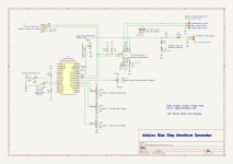
Here is my final circuit design. I added an option for using the internal Arduino 5V power as a bias voltage source. If 5V is sufficient, then an external bias supply is not needed. Just use a jumper at J4 to select the power source. The internal 5V can also be used in conjunction with POT5 to calibrate the voltage measurement ADC.
I'll check the PCB layout again and then it's order time.
The software is done as well.
I'll check the PCB layout again and then it's order time.
The software is done as well.
Attachments
- Home
- Amplifiers
- Pass Labs
- Frankentracer created