I'm reading along in Horowitz's "The Art of Electronics" and he states that a center-tapped full wave rectifier is inefficient and will require a larger transformer than a full-wave bridge rectifier.
Yet I see center-tapped full wave rectifiers in many tube amp power supplies. What gives?
It looks like you get more volts from the center-tapped arrangement — I'm guessing with corresponding less current? So is it a means to get higher voltage from a given transformer?
Yet I see center-tapped full wave rectifiers in many tube amp power supplies. What gives?
It looks like you get more volts from the center-tapped arrangement — I'm guessing with corresponding less current? So is it a means to get higher voltage from a given transformer?
said another way, for a given size of traffo, more power is available for FWB, the Audio Handbook by National SEmiconductors circa 1980 puts it at 30% more...
if you are getting off the shelf traffos from the ussual vendors, there is nothing much you can do...
for new designs, a fwb is better, traffos are easier to wind, insulation requirements not so stringent....
here is a good read.... powersupplies
if you are getting off the shelf traffos from the ussual vendors, there is nothing much you can do...
for new designs, a fwb is better, traffos are easier to wind, insulation requirements not so stringent....
here is a good read.... powersupplies
Yet I see center-tapped full wave rectifiers in many tube amp power supplies. What gives?
The forward drop in vacuum rectifiers is substantial. For example, it's a whopping 67 V. at the rated 250 mA. draw in a 5R4. As a doubled vacuum rectifier forward drop, which is the price of employing a bridge, is unacceptable, FWCT topology was "the only game in town".
A number of members, including yours truly, employ hybrid bridge rectifiers.
The quick answer is tube rectifiers, most of which are common-cathode, suited only to the FWCT circuit. If you used a full-wave bridge, at a minimum you'd need an additional rectifier tube with two separate cathodes. So you'd get better utilization of the transformer but lose another 30V or so in voltage drop in the second rectifier, plus the additional heater power. So the transformer won't be 30% smaller, maybe 10% by the time you're done...
For VERY low voltage, high current power supplies, a FWCT will have the advantage due to one less diode drop.
FWB or doubler makes the best use of a transformer, they're essentially equal except that the input caps in the doubler have to carry more ripple current.
For VERY low voltage, high current power supplies, a FWCT will have the advantage due to one less diode drop.
FWB or doubler makes the best use of a transformer, they're essentially equal except that the input caps in the doubler have to carry more ripple current.
Thanks for the response. I'll have to look into hybrid bridge rectifiers....
But see amps with diodes and still use center-tapped full-wave. I don't get that.
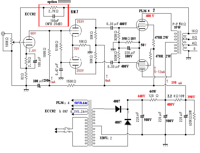
This one, for example, showed up in the forum feed just today for me:
http://www.diyaudio.com/forums/atta...w-full-construction-details-pl36-ppsch-02.jpg
(Thread: http://www.diyaudio.com/forums/tube...-amplifier-22w-full-construction-details.html)
But see amps with diodes and still use center-tapped full-wave. I don't get that.
This one, for example, showed up in the forum feed just today for me:
http://www.diyaudio.com/forums/atta...w-full-construction-details-pl36-ppsch-02.jpg
(Thread: http://www.diyaudio.com/forums/tube...-amplifier-22w-full-construction-details.html)
Thanks for the response. I'll have to look into hybrid bridge rectifiers....
But see amps with diodes and still use center-tapped full-wave. I don't get that.
This one, for example, showed up in the forum feed just today for me:
http://www.diyaudio.com/forums/atta...w-full-construction-details-pl36-ppsch-02.jpg
(Thread: http://www.diyaudio.com/forums/tube...-amplifier-22w-full-construction-details.html)
The power trafo could have been on hand.
The B- supply in the uploaded "El Cheapo" schematic employs a hybrid bridge.
Attachments

Thanks for the response. I'll have to look into hybrid bridge rectifiers....
But see amps with diodes and still use center-tapped full-wave. I don't get that.
This one, for example, showed up in the forum feed just today for me:
http://www.diyaudio.com/forums/atta...w-full-construction-details-pl36-ppsch-02.jpg
(Thread: http://www.diyaudio.com/forums/tube...-amplifier-22w-full-construction-details.html)
Hi Astera,
As AJT pointed out in post #2, it's not so much a question of efficiency as "what you can get off the shelf" that drives transformer selection. Most of the commonly available high-voltage transformers for tube design are supplied as center-tapped for full-wave rectification using two tubes. It's far less common to find single-winding (non CT) transformers that have the required voltage, and if you do you're probably going to need to get a separate transformer for the filament voltage (6.3 or 12.6) as the high-voltage transformers without CT generally don't have the extra windings for filament power.
As Eli pointed out, if you're using a tube rectifier the FW circuit using a center-tapped transformer is really your only option. Vinylsavor has an excellent example of a tube-based bridge design on his website, but such designs are not commonly used (it's not practical to use the "common" tube rectifiers such as the 5AR4, 5U4, etc. in a bridge circuit).
Many builders have opted to use silicon diodes instead of tube rectifiers in a FW supply. The topology is the same and and doing so allows use of HV transformers with integrated filament windings. Might have to juggle the transformer voltage a bit to come up with the same B+, as the silicon diodes drop FAR less voltage than tube rectifiers.
The advantage is that you can still use off-the-shelf transformers available from the usual vendors.
AJT has written about his transformers in (I believe) the Power Supply thread on this site, and he generally winds non center-tapped power transformers. But that's the key - he winds them himself, so he's in control of the topology. (BTW - it's worth checking out his thread on the sticky in the Power Supply section, he does beautiful work - it's inspiring!)
Us mere mortals who just buy transformers are stuck with what manufacturers sell, and that is generally a CT design. 😎
Sam

In a given transformer there is a certain amount of space for the secondary winding(s). To use much more or less than this will upset the balance between copper and iron losses, and the balance between primary and secondary losses. For a given secondary voltage you can either do one winding (and use a bridge) or have a CT which means twice as many turns in total. Twice as many turns means only half the cross-sectional area per turn because the winding still has to fit in the same space. Half the area means twice the resistance, so for a given current flow you get twice the power loss. To get back to the same power you have to drop the current to 0.707 as much i.e. a drop of about 30%.
As others have said, this was an acceptable compromise in the days of valve rectifiers with common cathodes. It meant only one diode drop instead of two - when a diode drop could be 10-50V. It also avoided the need for common-anode rectifiers which would have more complicated innards than common-cathode.
As others have said, this was an acceptable compromise in the days of valve rectifiers with common cathodes. It meant only one diode drop instead of two - when a diode drop could be 10-50V. It also avoided the need for common-anode rectifiers which would have more complicated innards than common-cathode.
even the single winding secondary can be used with tube rects in conjunction with silicon rectifiers, i do this a lot of times in my preamp builds and some power amp builds in the range of not more than 15 watt per channel...
Then again,
there is Ongaku...fashion or function?
Quad, Leak, Pye, Avantic, etc and they are all going abroad. 😕
And then there are guitar amps and sag..😉
Regards
M. Gregg
there is Ongaku...fashion or function?
Quad, Leak, Pye, Avantic, etc and they are all going abroad. 😕
And then there are guitar amps and sag..😉
Regards
M. Gregg
In a given transformer there is a certain amount of space for the secondary winding(s). To use much more or less than this will upset the balance between copper and iron losses, and the balance between primary and secondary losses. For a given secondary voltage you can either do one winding (and use a bridge) or have a CT which means twice as many turns in total. Twice as many turns means only half the cross-sectional area per turn because the winding still has to fit in the same space. Half the area means twice the resistance, so for a given current flow you get twice the power loss. To get back to the same power you have to drop the current to 0.707 as much i.e. a drop of about 30%.
As others have said, this was an acceptable compromise in the days of valve rectifiers with common cathodes. It meant only one diode drop instead of two - when a diode drop could be 10-50V. It also avoided the need for common-anode rectifiers which would have more complicated innards than common-cathode.
That's it in a nutshell.
Someone also mentioned full wave doubler (not the charge pump variety but half wave + and - in series. Efficiency-wize its the equivalent of the FW bridge but there is an oft-unmentioned caveat - ONLY if the filter caps have the exact same capacitance. And being electrolytic, in general they do not - so because the amount of charge transferred is different between the half-periods of the mains sinewave, there is a net DC flux in the transformer. Consequence: be careful when using doublers with a toroidal or R-core transformer.
The power trafo could have been on hand.
The B- supply in the uploaded "El Cheapo" schematic employs a hybrid bridge.
i use the hybrid FWB for the usual audio finals like the 6BQ5, EL34, 6L6Gc and KT88's,
for TV tubes like the 6LU8, 6AV5 and some transmitter tubes, i use the voltage doubler type, reason being that it is much easier to derive the screen voltages at 1/2 B+....
CT Tr + 2 diode fullwave rectifiers may be considered inefficient for the reason that they utilize half of the secondary in voltage, and the diodes require higher PIV (peak inverse voltage) rating.
Concerning hybrid supplies, could anyone speak to their experience in how they model the supply or approximate it in the Duncan Amps PSUD II tool? I was wondering how to calculate the B+ from a hybrid.
Hi!
I prefer the full wave bridge arrangement and use it in all my amps and preamps. When enough space is available with an all tube bridge using 4 TV dampers as rectifiers. If space is restricted I use hybrid bridges.
Thomas
I prefer the full wave bridge arrangement and use it in all my amps and preamps. When enough space is available with an all tube bridge using 4 TV dampers as rectifiers. If space is restricted I use hybrid bridges.
Thomas
perhaps today, traffo manufactures can sell their traffos with option for the user to do a full wave bridge or a center tapped full wave rectifier....very easy to do, just one additional lead...
Hi AJT,
a big advantage of the FWB for me is the possibility to have power transformers configurable over a wider range of secondary voltages.
Another advantage: take a scope shot of the secondary voltage with FWCT and compare it to FWB. You will see less disturbance with the bridge
Thomas
a big advantage of the FWB for me is the possibility to have power transformers configurable over a wider range of secondary voltages.
Another advantage: take a scope shot of the secondary voltage with FWCT and compare it to FWB. You will see less disturbance with the bridge
Thomas
Is that an indication of lower winding ESR, which would also then indicate higher crest factor current and likely more prone to higher frequency rectifier noise disturbance leaking out.Another advantage: take a scope shot of the secondary voltage with FWCT and compare it to FWB. You will see less disturbance with the bridge
Thomas
- Status
- Not open for further replies.
- Home
- Amplifiers
- Power Supplies
- Full Wave Rectifiers: Center Tapped vs. Bridged