How does the gate resistor value affect the waveform? Does a higher value cause the wave to slope up more vs straight up and down?
You need to balance the drive to the FETs vs the load on the drivers. Too much resistance and the FETs likely run hot (and eventually fail). Too low resistance and it loads the drivers (possibly to the point of failure).
In the image below, you can see the transient current in the drive circuit with various gate resistor values. You can see that the lowest value has the highest spikes in current.
In the image below, you can see the transient current in the drive circuit with various gate resistor values. You can see that the lowest value has the highest spikes in current.
Attachments
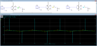

The gate is really just a capacitor. So you have an RC circuit. For a step voltage rise the peak current will be the step voltage / gate resistor value. So compare that with the current capability of the driver.
I see neither gates nor gate resistors, but I see bipolar transistors and load resistors? Go easy on me.In the image below, you can see the transient current in the drive circuit with various gate resistor values.
The FET gate acts much like a capacitor. The resistor between the EF pair (drivers) and the capacitor are basically the gate resistor.
If its a push pull output then gate resistors need to match to N and P channel mosfets.
Sometimes P channel mosfet has more capacitance so needs a slightly lower resistor value to match.
Sometimes P channel mosfet has more capacitance so needs a slightly lower resistor value to match.
It's just what I have on hand. I will just order 22ohm resistors. ThanksProbably not. Why do you want to increase the value?
I had someone tell me I was using the wrong gate resistors for 3205’s, I explained (and keep mind I am retarded) that they can range from as low as 20 ohm to 100 ohm for that Fet but claimed 47ohm was wrong and had to be 22ohm. Thing is, once you see many schematics that use 3205 they all seem to use 47-56ohm gate resistors. He claimed that the fet’s low RDS determines the gate resistacne. Just a few minutes of reading told me otherwise, fet’s gate is just a capacitor that charges to switch from open to close and vise versa. So the gate resistor (as Perry mentioned) controls the speed of the switching (no fhz but the slope). Now am not saying 22ohm won’t work but to say it is the right gate resistance because of the RDS value is kinda of silly to me but again am stupid, had he said it is due to the capacitance characteristics of the device being a specific number would’ve been a different story.
If the amp utilizes 1405’s and has 22ohm, then keep those resistors and fets In circuit. No need to change it to 47 or higher.
If the amp utilizes 1405’s and has 22ohm, then keep those resistors and fets In circuit. No need to change it to 47 or higher.
Last edited:
RDSon doesn't determine the drive requirements. The Ciss (for PS FETs) is typically the best to determine what it's going to take to drive it. Beyond that, you must test to confirm that the FETs are not running hot at idle at full duty cycle.
You will see that range of resistors used for the 3205s. Crossfire, Memphis, others used 22 ohm but that was relatively rare. 47 ohms was, by far, the most commonly used. 56 ohms was marginal. The 100 ohms typically only worked in amps with dead time programmed in. Kicker was one of the few I remember using 100 ohms.
You will see that range of resistors used for the 3205s. Crossfire, Memphis, others used 22 ohm but that was relatively rare. 47 ohms was, by far, the most commonly used. 56 ohms was marginal. The 100 ohms typically only worked in amps with dead time programmed in. Kicker was one of the few I remember using 100 ohms.
If it’s your amp you could piggy back an extra 47ohm to drop down the resistance to 23.5ohm.It's just what I have on hand. I will just order 22ohm resistors. Thanks
- Home
- General Interest
- Car Audio
- Gate resistors