Hi,
I'm still new to electronics DIYing, but I've got the gist of it down. Proper grounding just confuses the hell out of me. I guess I just don't get it.
Anyway. I have the parts to my LM3886 amp being shipped as we speak. I am using the Jim's Audio clone of the Yuanjing Lm3886 amp as well as some speaker protection etc.
I was orginally going to using an aluminum case but as I keep on adding more things to the amp (and to have space for future upgrades), the price of an aluminum case is too much. Instead, I plan on building a cheap wooden case and will do some sort of ghetto-mod to get some large computer heatsinks on each of the amp chips. Has anyone seen any negative effects of not screwing their amps onto a heatsink?
But onto the real question...
I have seen people use screw lugs and attach the ground wire to it, and then to the third prong on the IEC power connector. Why is it attached to the case as well?
If I had a wooden case, how would I get around this? Can I not just run the ground from wherever the amp needs to be grounded to the power jack? What does the case connection do?
Thanks. Sorry to sound newbish, but hey, I am.
Thanks again.
Nothing wrong with using computer heat sinks, but the chip must be firmly attached to the sink, using an isolator if the case is not isolated. I used these clips MAX08G Aavid Thermalloy Heatsinks on a chip amp without issue. Be sure that you don't drill through a heat pipe if your CPU heat sink has them.
The third prong of the IEC is a safety ground. It should be connected to all exposed conductive parts of your amp. If you don't have any exposed heat sinks, just connect your star ground to this pin. If you use something like a CL60 between the star ground and safety ground you will help break potential ground loops. You can also use a couple of diodes back to back and a 5R/3W resistor, like Pass does here: http://www.passdiy.com/pdf/a75p2.pdf (R17, D7, D8). A direct connection may work, depending on the rest of your system.
Have you looked at Apex Jr.Home Page for heat sinks? Steve's got a couple of options that are fairly inexpensive. They'd be less than CPU sinks unless you have them from dead machines.
Nothing wrong with using computer heat sinks, but the chip must be firmly attached to the sink, using an isolator if the case is not isolated. I used these clips MAX08G Aavid Thermalloy Heatsinks on a chip amp without issue. Be sure that you don't drill through a heat pipe if your CPU heat sink has them.
The third prong of the IEC is a safety ground. It should be connected to all exposed conductive parts of your amp. If you don't have any exposed heat sinks, just connect your star ground to this pin. If you use something like a CL60 between the star ground and safety ground you will help break potential ground loops. You can also use a couple of diodes back to back and a 5R/3W resistor, like Pass does here: http://www.passdiy.com/pdf/a75p2.pdf (R17, D7, D8). A direct connection may work, depending on the rest of your system.
Have you looked at Apex Jr.Home Page for heat sinks? Steve's got a couple of options that are fairly inexpensive. They'd be less than CPU sinks unless you have them from dead machines.
Thanks for the reply Bob. I will be using the isolated version of the LM3886 so the heatsinks won't be live. I have infact looked at Apex Jr. but I didn't realy see too much I liked in regards to heatsinks.
What exactly is the advantage of using a clip like that? If you don't want to drill into the heatsink or the place where the hole on the chipamp is is not optimal?
By star ground, do yo mean something like the picture I have attached. And then put a thermistor in line with the IEC prong and this star? (And what should this do?)
Could I make this easier by covering the bottom of the case with a piece of sheet of steel or something?
Sorry for being confusing.
Thanks again.
Attachments

Last edited:
I use the clips because it applies the pressure more evenly on the chip. If you look around you'll see a lot of people using bars across their chips and output devices to center the clamping force on the chip. Just using the tab may cause uneven pressure. Not purely necessary, but it makes me feel better.
Another advantage is that I can tap 6-24 holes instead of 4-40, which I find a little easier.
Yes, the thermistor goes between the star and the ground lug of the IEC.
If your heat sinks or any other metal parts are exposed at all they should be connected DIRECTLY to the IEC ground lug. This is a just in case safety thing. Should something come loose and the hot mains line touches an exposed part the fuse will blow rather than allow the part to remain hot for you to complete the circuit with your body. It doesn't matter whether the chip is isolated or not.
A ground star is better than a piece of sheet metal with various connections. You may find that you want to line your case for EMI protection, in which case that would connect directly to the safety ground.
Last edited:
I use the clips because it applies the pressure more evenly on the chip. If you look around you'll see a lot of people using bars across their chips and output devices to center the clamping force on the chip. Just using the tab may cause uneven pressure. Not purely necessary, but it makes me feel better.
Another advantage is that I can tap 6-24 holes instead of 4-40, which I find a little easier.
Yes, the thermistor goes between the star and the ground lug of the IEC.
If your heat sinks or any other metal parts are exposed at all they should be connected DIRECTLY to the IEC ground lug. This is a just in case safety thing. Should something come loose and the hot mains line touches an exposed part the fuse will blow rather than allow the part to remain hot for you to complete the circuit with your body. It doesn't matter whether the chip is isolated or not.
Thanks again. If you (or others) would just bare with me. I've got everything else down besides this whole grounding ordeal. I'm still learning so if I make dumb remark...well ya know...
So I guess I'll just be grounding the heatsinks anyway, Heaven forbid someone put their hand on the heatsink and got a nice 120V surprise.
Can I star ground in a wooden case? I would connect all the ground points to the star lug/bolt/bar and then could I run a big fat wire to the IEC with the thermistor inbetween? Would a metal chassis help?
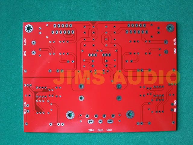
Also, another dumb question. This is the board that I will be using. It has 5 holes marked "GND". However, On the output sides the ground should be connected to the negative on the speaker, right? Not to the star ground?
On the holes marked In L and In R, should the ground be connected to the star ground?
Any other potential places to to ground?
I really don't mean to bother anybody and if you are not feeling up to answering, I totally understand. I'm just not confident enough with my electronics skills yet, and I don't want to blow up my amp, or do something stupid.
The third prong of the IEC is a safety ground. It should be connected to all exposed conductive parts of your amp.
If there are no exposed conductive parts, leave the safety ground out of the picture entirely.
se
If there are no exposed conductive parts, leave the safety ground out of the picture entirely.
se
What exactly is classified as an "exposed part"...like. I thought I got what he meant, but now maybe not...
Glad you're asking questions rather than build potentially hazardous equipment. Steve's suggestion makes a lot of sense if you are going to keep conductive parts away from hands. Helps avoid ground loops.
The board uses a ground plane instead of a star ground. I'd start with running a wire from the GND between the 28V terminals to the star lug and connect the PSU ground to the star lug. From there, CL60 to safety ground where it would meet up with the safety ground leads from the heat sinks (if needed).
Use the ground connections near the outputs for speaker returns, and the ones near the inputs as your only ground connection on your input jacks. Be sure that there is no other electrical connection between them. If you have hum problems move those four connections to the star, but I suspect that won't be needed.
An exposed part is anything conductive that you might touch except your input and output connections. So if you use CPU heat sinks inside the case and there's no way to touch them with the case closed, you can ignore the safety ground. If your heat sinks are on the outside of the case, safety ground them.
Last edited:
I'm going to try to whip a drawing to see if I am catching on to what you are saying. The PSU is integrated on board by the way.
You're overthinking it.
Are you building a wooden box with air holes and everything inside? If so, skip any connection to the safety ground, just connect the PSU ground pin on the board to the transformer center tap.
Or are you building a wooden box that has the heat sinks on the outside like many commercial amps? Then connect your PSU ground pin on the board to the transformer center tap and to safety ground along with the heat sinks.
Last edited:
I have attached what I've understood so far. The Output will be going to banana jacks. I will attached a cable from those banana jacks to the banana jacks on the speaker housing. The signal will then run through a 2-way passive crossover, and it will finally get to the speakers themselves.
Attachments

OK, fine. But the need for a connection to the green pin of your IEC at all depends on whether the amp has any parts that could potentially conduct mains power to the outside of its case.
Again, if your amp is like a wooden computer case with all the electronics inside, you don't need it.
Again, if your amp is like a wooden computer case with all the electronics inside, you don't need it.
You're overthinking it.
Are you building a wooden box with air holes and everything inside? If so, skip any connection to the safety ground, just connect the PSU ground pin on the board to the transformer center tap.
Or are you building a wooden box that has the heat sinks on the outside like many commercial amps? Then connect your PSU ground pin on the board to the transformer center tap and to safety ground along with the heat sinks.
Heatsinks are going to be outside of the case, so therefore they need to be grounded.
I revised that drawing. Perhaps you could give it a look. I'm still unsure as to where the signal Input grounds go...
Attachments

Last edited:
You can move the transformer "center tap" to the star, otherwise it looks fine. Does the board include a rectifier (or 4 diodes)? If not that changes your connections somewhat. Note that if your transformer has dual secondaries are both red and black the center tap will be one red and one black.
Assuming that you are using RCA jacks, the center poles are the signal, the shell connections go to the input ground.
Assuming that you are using RCA jacks, the center poles are the signal, the shell connections go to the input ground.
You can move the transformer "center tap" to the star, otherwise it looks fine. Does the board include a rectifier (or 4 diodes)? If not that changes your connections somewhat. Note that if your transformer has dual secondaries are both red and black the center tap will be one red and one black.
Assuming that you are using RCA jacks, the center poles are the signal, the shell connections go to the input ground.
Oi! That was my bad on the RCA plugs. Forgive me please.
It does have dual secondaries. I just made the two black to show that they are both going to ground.
The board does have 4 holes for a bridge rectifier.
I shouldn't move the heatsinks to the star should I? Directly to the safety?
Thanks for all of the help. I REALLY appreciate it. I know it's not easy trying to explain things to newbies. I'll hopefully have this thing done within a month or two.
Thanks again.
Enjoy your project.
I just wanted to make sure that you understood that you have to connect the secondaries out of phase to get the proper voltage.
I just wanted to make sure that you understood that you have to connect the secondaries out of phase to get the proper voltage.
I don't agree that your "except" is safe.Glad you're asking questions rather than build potentially hazardous equipment. ..............
...............An exposed part is anything conductive that you might touch except your input and output connections.
Can you explain how or why you arrived at those exceptions?
Exposed metal includes input and output connections. Unless you can guarantee Class 2 (double insulation) protection you need to use grounding. The idea is to make sure that two separate things have to fail before there is any danger to users. The mains transformer counts as one item, so assume that has failed and connected live mains to a secondary. Then you need to ensure that no other single failure (e.g. loose wire) causes danger.
OK, I guess I was wrong. SE's comments seemed to confirm my thinking. Thank you for challenging.
I'm just having a hard time wrapping my head around how one would isolate the secondary output (using DF96's transformer first failure example) and still be able to power the circuit. On the OP's board a transformer primary to secondary short would connect his ground plane to the mains. Would a separate bridge for each secondary winding be sufficient isolation to meet the standard?
I'm just having a hard time wrapping my head around how one would isolate the secondary output (using DF96's transformer first failure example) and still be able to power the circuit. On the OP's board a transformer primary to secondary short would connect his ground plane to the mains. Would a separate bridge for each secondary winding be sufficient isolation to meet the standard?
If your signal ground is somewhere connected to safety ground then a transformer fault should blow a fuse or trip a breaker. Separate bridges don't isolate anything.
There are two ways to be safe: full Class 2 isolation (almost impossible for DIY?), or grounding all external metalwork. Remember, it might not be you who gets killed, but one of your friends or family.
There are two ways to be safe: full Class 2 isolation (almost impossible for DIY?), or grounding all external metalwork. Remember, it might not be you who gets killed, but one of your friends or family.
- Status
- Not open for further replies.
- Home
- Amplifiers
- Power Supplies
- Ground Question with Wooden Enclosure.