Hi everybody!
I have one old Grundig SV2000 and I'm trying to fix it.
Only today I was able to test it properly for the first time but the right speaker doesn't work. The problem is not the speakers, I've switched the right with the left one and and the problem persisted.
So here I am asking for your help in trying to solve this.
Does anyone have the schematics?
Also does anyone have a clue of where should I start looking for the problem? (my first guess is that one of the amplifier circuits is not working)
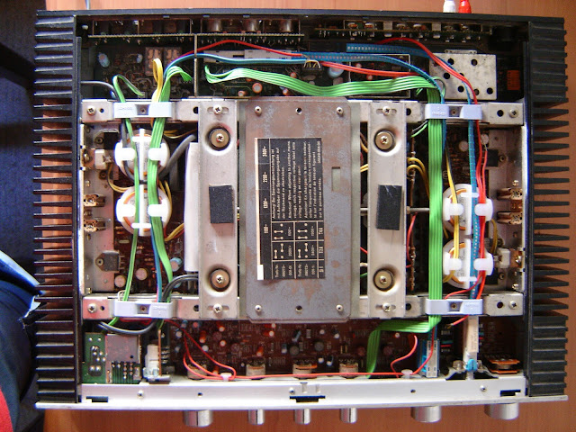
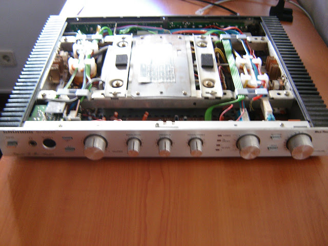
Here are some pics of the amplifier:
Best regards
PS: There is one similar thread about this subject, i've posted on it yesterday but it seems to be abandoned a long time. Hope no one gets mad because of this new thread.
I have one old Grundig SV2000 and I'm trying to fix it.
Only today I was able to test it properly for the first time but the right speaker doesn't work. The problem is not the speakers, I've switched the right with the left one and and the problem persisted.
So here I am asking for your help in trying to solve this.
Does anyone have the schematics?
Also does anyone have a clue of where should I start looking for the problem? (my first guess is that one of the amplifier circuits is not working)
Here are some pics of the amplifier:
Best regards
PS: There is one similar thread about this subject, i've posted on it yesterday but it seems to be abandoned a long time. Hope no one gets mad because of this new thread.
Is there an output fuse?
Is there an output realay?
...both these could be the source of the error.
If you can measure some small DC voltage (10-30mV) on the right output, then the poweramp could be working, and the error would be somewhere in the switches or the preamp.
Is there an output realay?
...both these could be the source of the error.
If you can measure some small DC voltage (10-30mV) on the right output, then the poweramp could be working, and the error would be somewhere in the switches or the preamp.
Hi Nrik!
Thanks for your quick reply. Yes there are two output relays and no output fuses. But anyway I guess the problem is really the amplifier. This Amp has output for two sets of two loudspeakers and in both of them the one who is not working is the right one.
Also I've measured a small voltage in the range you specified. But in the right one I've measured 4-5V!
It would really be great if someone could get the schematics of this Amp.
Thanks again!
Link to a service manual GRUNDIG SV 2000 GB U Service Manual free download, schematics, eeprom, repair info for electronics free of charge of course ;-)
first thing you need to do is to find out what i going on between main amp and pream ...best wayy is to seperate them ...
possible causes
faulty relays
faulty electrolytics ( amplifier area / protection area )
blown thermal fuses
blown outputs ( in this case you are in more trouble ...this one will be not easy )
leacky caps in amplifier area ...
though i dont like darligtons in the output the actual rest of the circuit has a really amazing potential to be a very nice amp
i could go for tip 142-147 as output replacements or try to find the Japanese cousins of them which i dont recall numbers but you will find them in panasonic sets expect that theJApanese are faster than the 142-147 pair ( always be carefull about the pins )
even sap 15 pairs could be option but this will be a hell of mod to make
the thing is that if you have output issues a replacement of outs is not going to be easy thing to do ...stabilizing darligtons can be tricky ....
remains a good thing that the rest of the circuit is very trickable so it can be done ...its a good amp .... go for it
Hi everybody!
Thank you aparatusonitus for the schematics I've been looking for them for a long time but never found them.
Also thank you sakis for the tips. Now I think I've got a good basis to start looking for the problem.
I'll post some news when I find some clue.
Thank you aparatusonitus for the schematics I've been looking for them for a long time but never found them.
Also thank you sakis for the tips. Now I think I've got a good basis to start looking for the problem.
I'll post some news when I find some clue.
Hi again!
I think I've found something...
As I expected, one of the output stage boards is not working properly. By now I've found two burn resistors and other two with the coating slightly damaged.
Here is a picture with the faulty resistors signaled with an X and the good ones but with the coating slightly burnt with a O.

Now I need to ask you a silly question... Should I replace the resistors now or should I first look for other faulty component witch made the resistors burn in the first place?
Also I'ts going to be a hell of a job to disassemble the board because of the heat sinks. I'll have to buy some thermal paste to replace the old one.
Again, thanks everybody for the help so far.
I think I've found something...
As I expected, one of the output stage boards is not working properly. By now I've found two burn resistors and other two with the coating slightly damaged.
Here is a picture with the faulty resistors signaled with an X and the good ones but with the coating slightly burnt with a O.
Now I need to ask you a silly question... Should I replace the resistors now or should I first look for other faulty component witch made the resistors burn in the first place?
Also I'ts going to be a hell of a job to disassemble the board because of the heat sinks. I'll have to buy some thermal paste to replace the old one.
Again, thanks everybody for the help so far.
Hi again!
Today I replaced the burnt resistors, and as I expected one of them burned instantly. It was R416. After it burnt I mesured aprox 30V in the terminals of the resistor.
So maybe there is something wrong with other component.
Also when I measue in the terminals of resistance R413 while in the circuit a resistance of 0.6K while on the other board I measure 1.8K. I disconnected the resistor and found there is nothing wrong with it, but maybe there is another faulty component.
Could someone give me an hint?
I'm sorry for the silly questions, but if there is someone that could help I would really apreciate.
Hi!
I've finally got the right channel to work. I've replaced two transistors, T404 and T405 with MPSA06 (one of them was in short circuit).
But now there is a slight distortion. The only thing I've changed was the four resistors and the two transistors. Now I'll try to find whats wrong.
If anyone has an idea of where to start looking, any help would be really apreciated.
 non english text removed by moderation
 - Status
- Not open for further replies.
- Home
- Amplifiers
- Solid State
- Grunding SV2000 Amp Repair