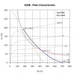
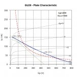
So I finally got around to building the GU29 amp. All went well save for two bad caps. I'm using a B+ of 440V, G2 of 200V, biased at 65ma. I was inspired by hendrixgr and his similar build. We both use SMPS and boost converters for power. I tapped off of the supply I built for my IA-2 (Integrated amp with 2 buffers, a headphone output, a phono stage, a line driver, and a 6P3S PP stage). It uses - you guessed it - toroidal power transformers as OPTs. A very nice sounding amp, indeed!
If anyone had any suggestions on improving the circuit, please feel free to comment! Oh, and the white wire near the meter has been tucked away since the photo 🙂
Cheers.
If anyone had any suggestions on improving the circuit, please feel free to comment! Oh, and the white wire near the meter has been tucked away since the photo 🙂
Cheers.
Attachments
Last edited:
Wow koda that looks very nice! Those GU29s are pretty awesome valves...
I certainly have no suggestions to improve the circuit, but have a question for my own edification. In my experience (admittedly limited, mostly of EL84s), the G2/screen is connected either to the primary supply (directly or through a resistor) or the secondary supply (likewise). Either way, it is usually within some tens of volts of the primary supply. Why is the G2 200V in this circuit, which is less than half the primary supply of 420V?
I understand that reducing Vg2 "squashes down" the curves, but I couldn't find a datasheet for this valve that has the pentode curves. Can anyone post a link to one?
Take a look at the datasheets, the G2 rating on the GU29 is quite a bit lower than the plate. Remember this is a RF transmitting tube, not an "audio tube".
OK thanks jazbo - now that you have pointed it out I see that the max Vg2 is 225V on the limited data sheet I could find
PS - with a bit of scratching around, I established that the 829B is an equivalent valve. Here is a link to the data sheet: https://frank.pocnet.net/sheets/049/8/829B.pdf
PS - with a bit of scratching around, I established that the 829B is an equivalent valve. Here is a link to the data sheet: https://frank.pocnet.net/sheets/049/8/829B.pdf
Last edited:
The load line looks a lot better but the bias is still way too hot.
Agreed - 35-40 mA would be better?
Am I missing something? 440V*0.065ma=28.6W -- well under the 40W limit?
EDIT: It's 65ma cathode current for both sections. Perhaps you thought I meant per section?
EDIT: It's 65ma cathode current for both sections. Perhaps you thought I meant per section?
Last edited:
Yes, I wasn’t clear on that, so I think you are fine - 32.5mA per section. Sorry for raising the false alarm...
...a question for my own edification. In my experience ... G2/screen is connected ...to the primary supply .... Why is the G2 200V in this circuit, which is less than half the primary supply of 420V?....
Different needs and tubes.
If you need HIGH! Peak plate current (class C, wild class B) then you want a tube of _low_ Mug2 for least restriction of the electrons. Such a tube will typically suck quite well with modest Vg2.
Now when you build the audio of a table radio (or jukebox, or hi-fi), you do not need HUGE current peaks, and you do not want the complication and cost of a solid lower-V G2 supply. These tubes are gridded for higher Mug2 so they may eat from the Plates' supply or a small drop from there.
You should also look around. Even tubes of high-ish Mug2 sometimes work G2 at half Vp. Find 6550 or 8417 working at 100 Watts output: ~~600V on plate, ~~300V on G2. (This made gobs of sense when low-volt Silicon rectifiers favored voltage-doubler supplies...)
829b in pp is an awesome amp.....g2 at 200 volts and b+ in the 400 volts,
a full wave voltage doubler is very well suited...
section matching can be a problem here....so that the 5894 is better being of single cathode construction although a bit lower plate dissipation...
a full wave voltage doubler is very well suited...
section matching can be a problem here....so that the 5894 is better being of single cathode construction although a bit lower plate dissipation...
It uses a 750W ATX power supply (in the PSU chassis) to drive 3 boost converters.
The B+ comes from one of these using a voltage doubler from 220V to get 440V (Isolated, installed in the PSU chassis): MINI DC-AC Inverter 12V To 18V220V/380V 500W Boost Step UP Power Module New Hot | eBay
The screen supply is coming from one of these (NOT isolated, installed in the amp chasis): DC-DC 8-32V to +-45V-390V Step-up ZVS High Voltage Capacitor Module Charge Board | eBay
And the bias voltage is derived from the 110V output of this lowered to about 55V with a Zener shunt regulator (Isolated, installed in the amp chasis): DC-AC Converter 12V to 110V 200V 220V 280V 150W Inverter Boost Board Transformer | eBay
This supply also powers an integrated amp.
Last edited:
could you explain more about your power supply design. I am interested
Bogen (and others) did this a lot on their PA amps. For instance, look at the M60A:

Notice the voltage doubler right at the PT.
There is another way if you have a PT with a center tap on the secondary. Rectify the taps on either end of the secondary with a bridge rectifier. The CT will now have half the voltage of the rectified voltage. Run it through a pi filter and there is your G2 voltage. I used a Triad isolation PT for a 12EN6 PP amp this way. Worked like a champ. B+ about 320V and G2 voltage half that. The best part is that the G2 voltage you get is stiff as a board. Very little variance with load. No further regulation necessary for most of us.
Different needs and tubes.
If you need HIGH! Peak plate current (class C, wild class B) then you want a tube of _low_ Mug2 for least restriction of the electrons. Such a tube will typically suck quite well with modest Vg2.
Now when you build the audio of a table radio (or jukebox, or hi-fi), you do not need HUGE current peaks, and you do not want the complication and cost of a solid lower-V G2 supply. These tubes are gridded for higher Mug2 so they may eat from the Plates' supply or a small drop from there.
You should also look around. Even tubes of high-ish Mug2 sometimes work G2 at half Vp. Find 6550 or 8417 working at 100 Watts output: ~~600V on plate, ~~300V on G2. (This made gobs of sense when low-volt Silicon rectifiers favored voltage-doubler supplies...)
Thanks PRR - very interesting. I will have a look at those just out of curiosity. I am quite new to valves and only really know the EL84 well for power valves. Because of limited availability, there are fewer "exotic" valves available in South africa and we seem to focus on the more common ones such as EL84, EL34, KT88 etc.
could you explain more about your power supply design. I am interested
full wave doublers...this is a nice piece by Patrick Turner..powersupplies
- Status
- Not open for further replies.
- Home
- Amplifiers
- Tubes / Valves
- GU29 push pull amp


