What is the advantages with a gyrator over a CCS in basic triode circuits..??
would they not behave exactly in the same way for any signal.??
would they not behave exactly in the same way for any signal.??
They may behave similarly for an audio signal, but differently for a signal at other frequencies.
A gyrator (as described in textbooks, and as usually understood by engineers) is a two-port device (like a basic transformer is a two-port: primary and secondary terminals), which presents to one pair of terminals and opposite of an impedance connected to the other pair of terminals. For example, it converts an inductance into a capacitance, and vice versa, which is very useful in making large high quality inductors without the expense of an equivalent wound component.
A gyrator is also useful for converting a high impedance into a low impedance (somewhat like a transformer does) but unlike a transformer it can do it down to DC (zero frequency) I needed a user-variable resistance that was adjustable from 0 to 1 ohm, accurately set. Pots like that are not cheap and not easy to find, so I did it with a gyrator, which used a few transistors to "gyrate" a cheap 10 kohm 10-turn pot.
Someone (can't think of his name right now) used a gyrator circuit to make a high performance filter for feeding filaments with pure DC. I think the term has been misused in audio forums since then.
Which is all a very long way to say your question cannot really be answered, at least not without looking at the actual "gyrator" under consideration.
Keit
As Keit says the "textbook" example of a gyrator is usually an opamp circuit that simulates an inductor with a capacitor. In many circuits like the active filters seen in graphic equalizers, it is a valid simulation.
The circuits often called a gyrator by tube amp builders and used as the plate load in a tube circuit do approximate an inductive load as far as frequency goes, IE the impedance goes up as frequency increases. They do not exhibit the magnetic energy storage properties of a true inductor, thus the plate voltage can not swing higher than the B+ voltage. In the circuit commonly found in tube designs the voltage on the mosfet's gate sets the plate VOLTAGE and the tube's bias sets the plate current.
The common CCS load for a triode will exhibit a more or less constant high impedance across frequency, and like the gyrator, the plate voltage can not swing higher than the B+ voltage. In a typical CCS loaded tube, the CCS sets the tube CURRENT while the tube's bias sets the plate voltage.
A tube (triode or pentode) with an inductance (single winding inductor, or transformer primary) is capable of swinging it's plate above the supply, approaching twice the supply in normal operation. The plate voltage can swing far above 2X the supply in cases where the tube is strongly overdriven such that it is cut off abruptly, like in a cranked guitar amp. I have measured 2000 volt spikes on the plates of the output tubes in a guitar amp operating from a 430 volt B+.
In a typical tube gain stage either of these can be used to provide more gain than a typical resistor load. The true inductor is best when maximum output voltage swing is needed. The "gyrator" or CCS can be used when size, or cost dictate. The choice of which depends on the situation. Do you need fixed plate voltage, or fixed plate current?
Tubelab's comments make complete sense, as he usually does. Except that:-
I recall some posts on diyAudio a few years ago.....
For an anode load, you can make a simple CCS that is const current only for AC (signal frequencies.) For DC it behaves as a simple resistance. For example, a bipolar transistor with a capacitor between base and emitter, and a bias resistor between base and collector. This behaves as a resistor equal to the bias resistor divided by beta (current gain of transistor) for DC but for AC it is very high impedance set by the transistor's Early effect. The transition from resistance to CCS with frequency is of course gradual.
You can do the same with a power MOSFET, which can perform rather better. Some people call this sort of thing a gyrator, but an engineer would not. The difference is that the impedance rises from the DC value with frequency until it levels off at the value set by Early effect. You would choose the capacitor such that it levels off at the lowest bass freq to be handled. As far as tube operating conditions go, its the same as a simple anode resistor. It is still resistive at AC once it levels off, so no phase rotation. You can use it with global negative feedback, as you can with any CCS.
In comparison, a true gyrator used to simulate an inductance has near zero DC impedance, and an inductive impedance that just keeps on rising with frequency, as high as you like, until it runs out of puff. Its impedance is always inductive, causing the signal to be rotated 90 degrees (so don't do it with negative feedback).
Keit
Last edited:
PS: Early effect: Named after an engineer named Early. The current gain of a bipolar transistor is roughly proportional to collector voltage. This is what primarily sets the output impedance of a common emitter stage at low (ie audio not RF) frequencies, and is a cause of much distortion in the driver stages of transistor amplifiers. Similar to what happens with pentodes but not the same.
Keit
Keit
Last edited:
I understand the concepts of a gyrator, and as far i I see CCS and gyrator behaves much in the samen manner when it comes to function with audio signals. from a signal point of view they both contributes a close to infinity large resistor and as such the impedance of the following stage sets the impedance (in parallel with the dynamic anode impedance) on which the tube current is modulated. as both ar close to infinity, should the not behave the same..??
Off course a major difference is that with gyrator the tube (anode resistance) sets the current, Not so with the CCS where the current is forced by the CCS.. But would that not just give us more options to pay with..??
Off course a major difference is that with gyrator the tube (anode resistance) sets the current, Not so with the CCS where the current is forced by the CCS.. But would that not just give us more options to pay with..??
Last edited:
CCS sets the dc plate current (and lets the tube choose its plate voltage)
CCS tries to establish a horizontal load line (which gets modified though when loaded)
CCS will not work on top of a pentode (which is sort of a CCS itself)
gyrator tries to set plate voltage (approximately and lets the tube choose the current)
(this may help to keep operating points more stable with different tubes and when tubes age)
gyrator should establish something like an elliptical load line (similar to reactive load)
gyrator can be put on a pentode (if you can tame stability issues from high gain)
Because load lines of CCS and gyrator intersect differently with plate curves and react differently to load conditions, distortion etc should be somewhat different; whether you can hear any difference ... try both and tell us ...
I understand the concepts of a gyrator, and as far i I see CCS and gyrator behaves much in the samen manner when it comes to function with audio signals. from a signal point of view they both contributes a close to infinity large resistor ......
Well, no, they are not the same. This was one of my points:-
As Sorento said, a CCS gives you a straight horiz load line, a gyrator gives you an inductive load (not infinite) thus an elliptical loadline.
But, per my other point, gyrators aren't necessarily gyrators - the term is misused in audio forums. What some people call gyrators are actually AC coupled CCS's. Which one are you actually considering?
As a circuit can be designed to behave as a CCS (or a gyrator for that matter) at signal frequencies, but as a resistor, or a CCS, or a CVS, at DC, the posts by Sorento and others about what controls anode voltage or anode current are not necessarily correct. You can use a CCS with a pentode (its been done for decades), provided it behaves as a resistor or CVS at DC.
Keit
Last edited:
CCS's were used with pentodes in 1940's and 1950's EEG and ECG machines, where extreme gain was required with high reliability (thus minimal tube count required). To make the CCS, another tube was required, but the gain obtained was huge, better that 2 tubes cascaded.
Stability was not an issue because the bandwidth required was very low, a few 10's of Hz at most. Simple shunt capacitors tamed it.
One or 2 cheap and nasty PA amplifiers in the 1950s also used CCS with pentodes to get the most gain out the fewest tubes. Bandwidth was good enough for PA but not for hi-fi.
Keit
But would that not just give us more options to pay with..??
Yes, I tend toward using a mosfet based "gyrator" circuit with the gate tied to a fixed voltage through a high value resistor in cases where DC coupling to the next stage is used. The value of this resistor is effectively in parallel with the "gyrated" inductor and can be used to set the maximum plate load impedance.
You can get really high stage gain when using this trick with a pentode. In practice microphonics will become the limiting factor with high stage gains, but 40db+ is possible with high Gm tubes. The capacitor from the tube's plate to the mosfet gate will set the frequency of the high pass pole. Often this capacitor will get quite large where high stage gains are desired. This will in turn require a longer time for the DC operating point to stabilize.
I tend to use a CCS load when attempting squeeze the maximum gain out of a triode and the exact value of plate voltage is not important, or can be adjusted by the tube bias. As with the gyrator, a resistor in parallel with the CCS (or the input impedance of the following stage) can be used to lower the plate load impedance. A CCS alone will force the circuit's gain to be dependent on the tube's characteristics alone, and a wide tube to tube variation is seen with some tubes.
Any time you are trying to squeeze the most gain out of a tube by increasing its load impedance, the characteristics of the tube itself become the dominant factor in the DC and AC performance of the stage. The gyrator and CCS are two options which can be used to force the plate voltage (as does the inductor) or plate current.
mosfet gyrator over triode has simplicity benefit - you just adjust Ua for tube, and then Rk for desired current.
important when using vintage tubes, with 150V max... i often just put 2 equal resistors Ua= 1/2 Usupply
enhacement fets are easier to find
fet ccs -you adjust for desired current; then you must adjust Rk to have desired Ua (adjusting current for fet and for triode)
in both cases, driver tube sees high Z; and low Z is at output. unobtainable with Ra.
loadlines are more horizontal, gain = µ (almost); THD minimal.
low Cgd FET is the key in both cases.
One or two supertex DN2540 depletion mossfets and a few resistors makes for a very simple CCS setup. gyrator takes a few more.
I am looking to make a DHT type preamplifier, with my eyes for now set on the 3A5/DCC90 tube. so something like 110V supply and a 10mA current. (two sections tied together) filament biased@3V..
I am looking to make a DHT type preamplifier, with my eyes for now set on the 3A5/DCC90 tube. so something like 110V supply and a 10mA current. (two sections tied together) filament biased@3V..
One or two supertex DN2540 depletion mossfets and a few resistors makes for a very simple CCS setup. gyrator takes a few more.
I am looking to make a DHT type preamplifier, with my eyes for now set on the 3A5/DCC90 tube. so something like 110V supply and a 10mA current. (two sections tied together) filament biased@3V..
Look at Ale Moglia's gyrator on the Bartola Valves site. It's a really good one for a DHT preamplifier stage. Favourite tubes for this are 01A at 3mA or 2P29L at 15mA if you need more current e.g as driver. I've built a few of these and they sound great.
Just so this is clear:
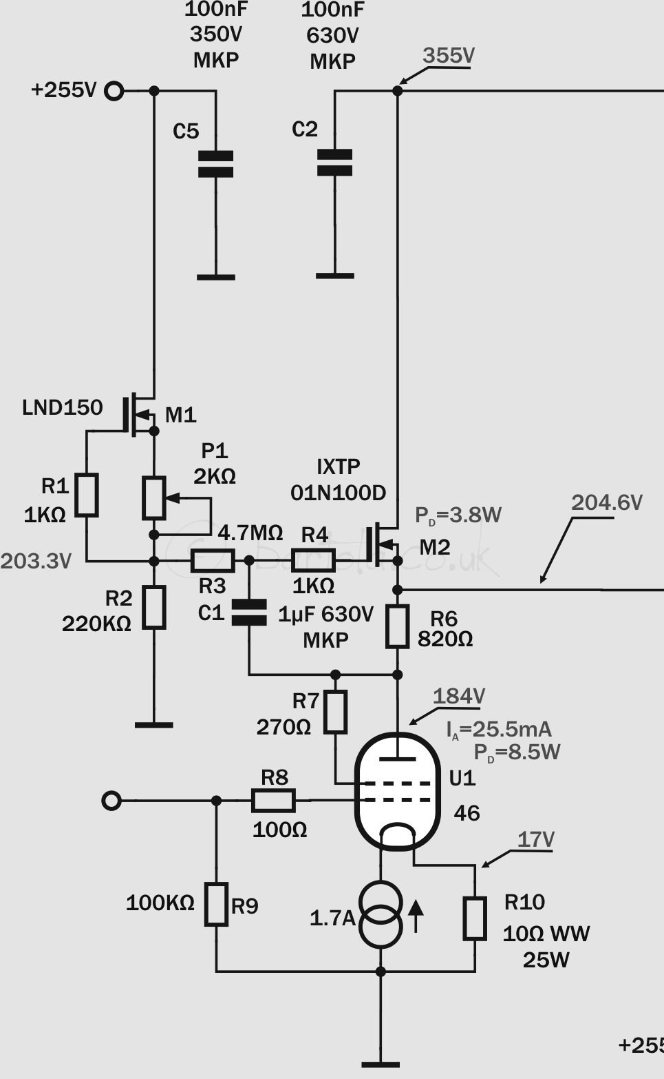
The circuit posted by hpeter is a CCS, not a gyrator.
It is as I said: It behaves as a CVS at DC, setting the anode voltage to approx. that of the first MOSFET gate supply, but the 1 uF capacitor off the tube anode makes the second MOSFET gate-source voltage constant for signal frequencies, so the drain current is constant and thus the dynamic anode load is very high - a CCS.
Keit
Last edited:
Yes, "gyrator" is a general thing of many faces.
In this crowd, I assumed "gyrator" was an "inductor" faked with a capacitor and an amplifier. That's by far the most likely meaning.
I am sorry for the imprecision.
I suppose in this place, someone has gyrated a coil into a fake cap, or a resistor into a negative resistance. Ma Bell used negative resistances as line boosters, though being practical men they used amplifier formulas not full gyrator theory.
The CCS usually works OK for triodes because the triode+RK is a perfectly good resistor, and CCS+R will tend to find a balance if CCS is not impossibly large or tiny. For pentodes there is little leeway.
The CCS will work all the way to DC. The (fake coil) gyrator will add a bass-cut, which must be considered especially in NFB stability.
I should have said the first MOSFET is used as a constant current supply for the 220 k resistor, and thus the second MOSFET gets a constant bias voltage from this resistor and thus behaves as a CVS for DC but a CCS for signal frequencies.
The diyAudio software on my laptop meant I had to look at the circuit, and then type from memory of it.
Keit
The diyAudio software on my laptop meant I had to look at the circuit, and then type from memory of it.
Keit
- Status
- Not open for further replies.
- Home
- Amplifiers
- Tubes / Valves
- Gyrator or CCS