I have an HK citation 24 on the bench, and I've been told by the guy who gave it to me that it wasn't working. I'm assuming from what I've read that there is a capacitor in there that goes bad and keeps it from coming out of the protection mode when it turns on.
I've measured with an ESR tester and found a number of small electrolytics that seem to have high ESR, though I haven't checked any out of circuit yet to verify.
Does anyone know which capacitor is the one in the control circuit that keeps down the speaker thump when you turn the amp on? I have the full schematic and repair manual
I've mostly ever worked on tube stuff, so any tips on things to watch out for with this would be welcome.
It looks like the main board is actually the same as for the Citation 22, has anyone dropped in the extra few output transistors and related parts and turned this into a 200W amp?
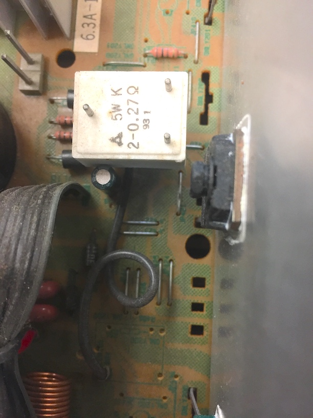
I also found what seems to be a very poorly placed capacitor (C428, next to resistor R488), and was wondering If maybe this should be a littler farther away from that big old 5W resistor. See attached photo:
I've measured with an ESR tester and found a number of small electrolytics that seem to have high ESR, though I haven't checked any out of circuit yet to verify.
Does anyone know which capacitor is the one in the control circuit that keeps down the speaker thump when you turn the amp on? I have the full schematic and repair manual
I've mostly ever worked on tube stuff, so any tips on things to watch out for with this would be welcome.
It looks like the main board is actually the same as for the Citation 22, has anyone dropped in the extra few output transistors and related parts and turned this into a 200W amp?
I also found what seems to be a very poorly placed capacitor (C428, next to resistor R488), and was wondering If maybe this should be a littler farther away from that big old 5W resistor. See attached photo:
Attachments

From what I could find from the service manual (schematic and layout diagrams mis-cropped and multipage in the pdf alas), PCB-5 is the protection board, and its seems to be quite small.
Given its 30 years old or so I suspect a lot of electrolytics could be replaced to good effect once the fault is sorted.
Given its 30 years old or so I suspect a lot of electrolytics could be replaced to good effect once the fault is sorted.
Muting is by Q401, 402, 417 and 418 all controlled by Q3. The only electrolytic capacitors in the circuit are C12 which is part of the small power supply for the circuit and C11 which along with R13 is the time delay.
Craig
Craig
I also have one citation 24 and it's been 8 years since I worked on it that I calmed down and I still have not found the (the) problems.
I will follow your lead and help if I can, good luck
I will follow your lead and help if I can, good luck
I also have one citation 24 and it's been 8 years since I worked on it that I calmed down and I still have not found the (the) problems.
I will follow your lead and help if I can, good luck
Hopefully it's not the blind leading the blind!
🙂
From what I could find from the service manual (schematic and layout diagrams mis-cropped and multipage in the pdf alas), PCB-5 is the protection board, and its seems to be quite small.
Given its 30 years old or so I suspect a lot of electrolytics could be replaced to good effect once the fault is sorted.
I'm of the mind to shotgun them all, but most are testing well withing spec for ESR, just some small ones that not really be so bad...
From what I could find from the service manual (schematic and layout diagrams mis-cropped and multipage in the pdf alas), PCB-5 is the protection board, and its seems to be quite small.
Given its 30 years old or so I suspect a lot of electrolytics could be replaced to good effect once the fault is sorted.
HIFI engine has the service manual, plenty clear enough to see the whole thing. nice copy overall.
Muting is by Q401, 402, 417 and 418 all controlled by Q3. The only electrolytic capacitors in the circuit are C12 which is part of the small power supply for the circuit and C11 which along with R13 is the time delay.
Craig
Thanks! I'll look closer at this. I read about this being a relatively simple problem to cure.
No blown fuses, no burnt spots found so far. If C11 doesn't charge properly, I think it never stops muting, if I've understood this all correctly. so no noise or sound comes out.
C12 is giving my ESR meter a fit, so I'm going to remove it and test out of circuit. C11 seems to be working.
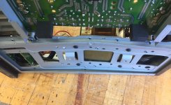
The transformer mount looks badly bent, but it is so symmetrical that it must have come from the factory this way. zero damage to the bottom cover. Maybe this was to make the mount slightly rigid and reduce hum from the transformer? Someone else in another thread re-mounted with rubber grommets, which I may do at some point if it all ends up working.
onward to remove C12 and check it out of circuit.
Attachments

C12 reads proper out of circuit, but C11 is doing odd stuff, reading higher hooked up to the tester one way vs. the other (two different cheapie ESR meters experiencing the same issue.) Sometimes, it reads very low, as in picofarad low. Looks like maybe there is some corrosion on the legs up near the body of the capacitor, but hard to see.
Unfortunately no caps of this value currently in the junk box to test with, so time to place mouser order soon, and get things ready for some other projects I want to finally make happen.
Unfortunately no caps of this value currently in the junk box to test with, so time to place mouser order soon, and get things ready for some other projects I want to finally make happen.
You can cheat a bit to see if the caps are the problem. If C11 is larger the time delay is longer, if C12 is larger the power supply won't collapse immediately when the amp is tuned off and you might hear the main supply start to collapse before the relay de-energizes.
Craig
Craig
You can cheat a bit to see if the caps are the problem. If C11 is larger the time delay is longer, if C12 is larger the power supply won't collapse immediately when the amp is tuned off and you might hear the main supply start to collapse before the relay de-energizes.
Craig
If C11 was open circuit or close to it, would that have prevented the muting from turning off?
I can drop in another close-ish value for C11 and see what happens. I don't have a handy preamp at the moment to control volume. Can I drive with mp3 player headphone jack to RCA inputs, and just keep the volume on that very low so as to test with lower wattage speakers rather than risk some nice ones?
It was brought to my attention that the protection timing cap is C11, a 33/10V cap if faulty won't come out of protection. You may have figured it out by now.
I an curious as to what you have for c12 ? I have a Citation 22 it lists a 33mfd/50v yet on the schematic and in the amp its a 10mfd/50v . I have no issues just wondering what others have in that spot. thanks
I an curious as to what you have for c12 ? I have a Citation 22 it lists a 33mfd/50v yet on the schematic and in the amp its a 10mfd/50v . I have no issues just wondering what others have in that spot. thanks
when I had mine, it was in the same state (protection), an output transistor was visibly exploded, so I desoldered all the output transistors and I turned on the amp.
it did not trigger, so I bridged to power the circuit and see what I had at the solder pads of the output transistors.
from there, I was able to determine that the half of the drivers were in short circuit, I thus untied them and there, the amp and out of protection, I then could easily find the culprits and put it back in service.
it worked well for 4 years and then one day it went into protection after a thermal runaway.
I put out the circuit "hight current" and it is going back in the order but of of I put the circuit "hight current" on "one" it restarted in thermal runaway.
Then, a few months later, he began to emit "ploc" and crunching noises.
since, I'm looking for ...
It was brought to my attention that the protection timing cap is C11, a 33/10V cap if faulty won't come out of protection. You may have figured it out by now.
I an curious as to what you have for c12 ? I have a Citation 22 it lists a 33mfd/50v yet on the schematic and in the amp its a 10mfd/50v . I have no issues just wondering what others have in that spot. thanks
Citation 24 has C11 as 33µF/10V, C12 is 10µF/50V, and that is what is in place in both instances.
when I had mine, it was in the same state (protection), an output transistor was visibly exploded, so I desoldered all the output transistors and I turned on the amp.
it did not trigger, so I bridged to power the circuit and see what I had at the solder pads of the output transistors.
from there, I was able to determine that the half of the drivers were in short circuit, I thus untied them and there, the amp and out of protection, I then could easily find the culprits and put it back in service.
it worked well for 4 years and then one day it went into protection after a thermal runaway.
I put out the circuit "hight current" and it is going back in the order but of of I put the circuit "hight current" on "one" it restarted in thermal runaway.
Then, a few months later, he began to emit "ploc" and crunching noises.
since, I'm looking for ...
From my experience with other gear, I'd start replacing all of the electrolytic capacitors at that point. They seem the most failure prone of all of the parts. But there may well be other damage to parts that got cooked if any of the electrolytic capacitors failed. I hope you can get it sorted!
very honestly, it's been a long time since I stopped looking.
I keep it for when I have nothing to do, but I think it will never happen.
I replaced more than 80% of the chemical capacitor and controlled almost all transistors without finding anything.
it is part of my list of "strange cases" with my Proton AA2120.
on the other hand, if you need parts, I would be happy to dismount and send them to you.
So I haven’t had time to mess with this in a while, but replacing c11 did bring it out of protection mode. I found some cold solder joints when doing this, and reflowed those. Can’t remember where they were, but it was on some transistors feeding into the end stage, and was making setting the bias very flakey. Still planning to replace all of the e-caps since I have the lid off, and they’re not getting any younger.
Wondering if anyone can confirm that the transformer mount has been bent on mine or if it is supposed to look like that? I don’t want to mess things up by trying to fix something that is not broken!
Also still wondering if there is anything to upping the wattage to citation 22 levels besides adding in the missing power transistors and resistors on the board? Will I need a different power supply transformer too? 100wpc is probably plenty, but I’m wanting the extra watts to be able to power some relatively inefficient speakers down the line.
Last edited:
- Home
- Amplifiers
- Solid State
- Harmon Kardon Citation 24 repair