I am curious if anyone has modified this phono pre-amplifier. Specifically op amp, or capacitors? if you have, I’d love to hear about it


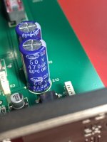
Here are pics of mk5
Attachments


Well they've used NE5532A rather than two NE5534A's, which is a shame as that seems a dumb way to save 30p on costs.
Unless you have a hot-air rework station I'd strongly recommend against any attempt to change opamp - even so it will be tricky to avoid melting the through-hole caps in the process. OPA1656 might be an upgrade, but the decoupling requirements might not be met by the current circuit...
Unless you have a hot-air rework station I'd strongly recommend against any attempt to change opamp - even so it will be tricky to avoid melting the through-hole caps in the process. OPA1656 might be an upgrade, but the decoupling requirements might not be met by the current circuit...
Looks like ±1% (or better) tolerance resistors, so likely metal film. Film caps. That seems reasonably competently put together, so I'm curious what you'd expect to gain by changing those components.
Tom
Speaking of... I'm not seeing a decoupling cap by V- of the NE5532. Rather that pin appears connected to ground with two vias. That makes me wonder if it's operating on a single supply. If I was to do something different with the circuit, I'd put it on a split supply, but of course that'll require a board spin.but the decoupling requirements might not be met
Tom
Speaking of... I'm not seeing a decoupling cap by V- of the NE5532. Rather that pin appears connected to ground with two vias. That makes me wonder if it's operating on a single supply. If I was to do something different with the circuit, I'd put it on a split supply, but of course that'll require a board spin
Your are quite correcect - Look at the PSU part at the upper left. A single LM317 for power regulation. With Rega supplying 24V AC to the circuit from one of their tiny Wall-warts, it would not have taken all that much extra effort to generate a +/- supply. Goes in-line with using a 5532 for second stage I guess.
Other thing a notice is that this is a two stage circuit with passive lowpass between the stages and active bass-boost with the 5532.
I have not modified this circuit myself so I can offer no definitive advice, but if was mine and I was to modify it I would start by looking at the PSU section and the op-amp used in the second stage. Given a single ended input stage (probably NPN 2SC5343E) and 5532 second stage with its limited PSRR at higher frequencies there may be a possible improvement in reducing rectifier noise.
I would consider swapping the diode bridge for individual diodes (for example Schottky diodes) and possibly putting a .film capacitor across +/i leads (in parallel with one of the blue 470uF/50v caps).
Before you change op-amp, check what voltage it is operating on by measuring between pins 4 and 8. If it is below 36 volts you should have a good choice of alternatives.
If you feel confident soldering SMD you could try a better performing op-amp OPA1612, LM4562, OP1642, OPA1656 could be alternatives, just make sure whatever you chose is OK without splitt supply
Last edited:
I haven’t found a schematic anywhere but I’ll keep looking. Great information. I am competent working with surface mount and an iron but you guys got me on the EE. i picked this up used and cheap and it sounds transparent an is a reasonable preamp in the $200 range so I felt like they built a $100 phono stage and sell it for $450. I was hoping there was some basic architecture to work with and have some fun modifying and getting more out of.
I doubt there's much to gain by that, but if you were to go that route, I'd look at some of the synchronous rectifier options available.I would consider swapping the diode bridge for individual diodes
Personally, I'd probably go after the LM317. Swap it for one of the more modern and ultra-low noise LDOs from TI. TPS7A-series for example.
Tom

- Home
- Source & Line
- Analogue Source
- Has anyone modified a Rega Fono MM Mk3 or Mk5