I have a Fluke 87V Meter.
The resistance measurement is not accurate. The reading is well below the correct value.
Could you guys tell me how to fix this ?
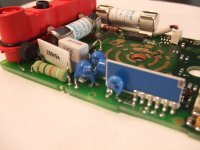
Someone suggested changing the capacitors. I opened up the meter but couldn't tell which are the capacitors. Maybe you guys can tell point them out.
The resistance measurement is not accurate. The reading is well below the correct value.
Could you guys tell me how to fix this ?
Someone suggested changing the capacitors. I opened up the meter but couldn't tell which are the capacitors. Maybe you guys can tell point them out.
Attachments


Pardon me mentioning the obvious, but did we check that the battery in the meter was fully charged?
I'm familiar with Fluke products and calibration. Is the ohms function the only things that is suspect? Let me know I would like to help you.
Kind Regards,
Perry
Kind Regards,
Perry
That is a great point.
That battery has been in there for 2 years.
Since other measurements are fine, I didn't think about the battery.
That battery has been in there for 2 years.
Since other measurements are fine, I didn't think about the battery.
Check and see where it loses accuracy. Try measuring some known values like 10 ohms, 1k, 100k, 1M etc. When we get meters calibrated at work they check every scale.
Check the board for something obvious like a bad solder joint. Changing out parts that aren't bad could worsen the accuracy.
Check the board for something obvious like a bad solder joint. Changing out parts that aren't bad could worsen the accuracy.
I've got several ideas. Also if the batter was the problem the display window would show a battery symbol. The meter does monitor the battery level.
Let me know if I can help.
Thanks
Perry
Let me know if I can help.
Thanks
Perry
Hi manp111,
You do realize that you may cause far more damage than you imagine by working on this - right? You have there one very accurate meter.
Having said that, this meter uses a Kelvin setup for resistance measurements. The contacts in the terminal assy are split electrically. Also, the divider for most of the ranges is a thick film unit. Anything wrong there would affect everything. Also, don;t mess around with capacitors.
Most of the parts used on the jack side are rated for leakage and may be designed to break down as a safety measure. You really need to use the exact parts from Fluke. The PCB is also supposed to be contaminate free. Wash off all flux and finger marks before sticking it back together. Now, for the positive stuff ...
If the terminal assembly has or had fluid leakage, you may be able to carefully remove the terminal block as a unit. Be extremely careful as you can destroy the meter. Carefully clean the PCB under the terminal assy. Carefully clean the bottom of the terminal assy and also (especially) the contacts inside. You don't want to see green stuff. The final clean is done with 99% alcohol. Make sure all blemishes are removed as they may be current leakage paths. I have seen a few mode switches (that big round thing in the middle) cause trouble, a gentle cleaning is all you can do there. Lubricate the points that are subject to wear.
Lastly, the resistance readings are taken by passing a known current through the resistance and measuring the voltage. If the current source is out, forget calibrated resistance readings. Have a look on the PCB for corrosion or any signs of fluid. Wash with your 99% alcohol. It might be a good idea to check for service from Fluke as they have been known to replace an entire meter for the cost of the service. I don't know what the current policy is, so check.
Perry is right about the battery symbol. Always use the best quality batteries you can get (remember how much that meter is worth!).
-Chris
Get some 1 % resistors of different values (any small wattage is OK). Using the two terminal test (not the Kelvin) test the resistors by poking straight into the meter connectors. Don't use any test leads.
I agree...that was a respectable and not inexpensive instrument when new and fully functional. It's quite a bit more sophisticated than say, a 1960's vintage VOM, something you could probably get way replacing parts in and re-calibrating simply.
Good luck. I agree with the suggestions implying double and triple checking with independent methods to be sure it's not something simple before you end up with a Franken-meter.
It had the ability to protect itself to some extent if someone applied voltage to the ohms input, and I believe made an audible alarm when a charged capacitor or voltage source was applied to the ohms input. If someone applied a high voltage like ac line or a tube power supply...it may have exceeded its self-protective capability (assuming there is not something simpler misleading you).
Obviously since you have/had it apart, you could look/smell for damage...which may not always be visible.
I have a 4-1/2 digit inexpensive DMM with black soot inside the housing...not encouraging...but some features seem to work fine....and others not - AC V reads about 1/2 normal. Too inexpensive to repair, not broken enough to give up one :O)
For example, some of the speaker drivers are 11 ohm. My Fluke 87V shows 7 ohms.
The specified impedance of a speaker driver is NOT the same as the DC resistance (what your meter measures).
Get some 1 % resistors (or even better 0.1 % resistors). As others suggest, get 1.00 ohm, 10.0 ohm, 100 ohm, 1.00 kOhm, 10.0 kOhm, 100 kOhm, 1.00 Mohm, and 10.0 Mohm. Even if you buy them locally (assuming you have a well stocked electronics store nearby), that's only about $1 worth of resistors. Measure them all and verify that the reading is within +/-1 % of the specified value.
Even better, you could find a lab that does calibration of meters and have them calibrate it for you. That'll probably set you back about $100...
Also, the meter should read close to zero ohm when the test leads are shorted together. My 6-digit meter reads 0.2 ohm (the resistance of the leads themselves).
Don't mess up your meter because you measured an 8-ohm speaker driver and it didn't read 8.0000000 ohm, OK?!
~Tom
- Status
- Not open for further replies.
- Home
- Amplifiers
- Tubes / Valves
- Help: Fluke 87V Meter Calibration