Hi All.
I came across the loose pair of single ended output transformers in the photos below, and I am hoping that someone will recognize them and be able to tell me something about their origin.
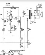
Also, I have a question about how they are wired. I have attached a hand drawing of their wiring that includes the measured resistance between the terminals. What was the purpose of the resistor and capacitor on these transformers in the original circuit? Why is there three wires coming out of the primary (red wires) side of the transformer? Can I remove the capacitor and resistor, and use the full primary and secondary windings? I would like to use these OPTs in a 6V6 SET amp I am building. Any advice or insight would be much appreciated.
I came across the loose pair of single ended output transformers in the photos below, and I am hoping that someone will recognize them and be able to tell me something about their origin.
Also, I have a question about how they are wired. I have attached a hand drawing of their wiring that includes the measured resistance between the terminals. What was the purpose of the resistor and capacitor on these transformers in the original circuit? Why is there three wires coming out of the primary (red wires) side of the transformer? Can I remove the capacitor and resistor, and use the full primary and secondary windings? I would like to use these OPTs in a 6V6 SET amp I am building. Any advice or insight would be much appreciated.
Attachments


Might be the photo.. but they look a little charred?
Do both transformers measure the same?
A little about the company:
Wiki
Similar transformer here on RadioMuseum.org:
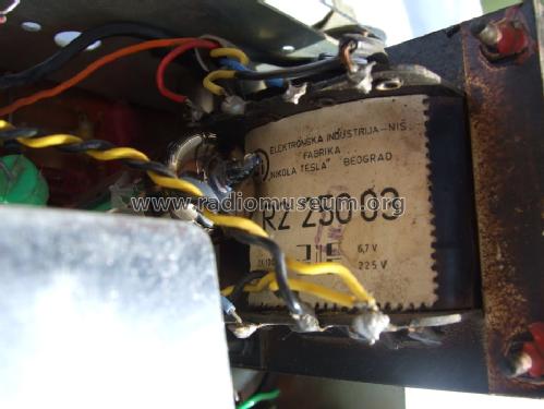
The three wires on the primary side may have been to allow for 110/220v selection.
Those transformers are likely to be very old and in unknown condition. Ask yourself if they are really worth salvaging.
Do both transformers measure the same?
A little about the company:
Wiki
Similar transformer here on RadioMuseum.org:
The three wires on the primary side may have been to allow for 110/220v selection.
Those transformers are likely to be very old and in unknown condition. Ask yourself if they are really worth salvaging.
Last edited:
They seem to be in good shape, and don’t look or smell charred in real life. They are very solidly built. They are gapped like single ended output transformers normally are, so I don’t think they are power transformers.
I don’t think they are power transformers.
Apologies, you did say they are output transformers.
This is my guess:
The 470 pf capacitor is connected in parallel to the primary. The extra terminal with the red wire is a portion of the primary used as a choke surrogate and you can left it unconnected. The 48 ohm resistor is connected in parallel to the secondary. The central terminal is ground, the white wire is the feedback output for a fancy tone control as they used to build it in the German radio of the '50. The original speaker had 3-5 ohms output impedence. Power was 3W or 5W according to the size, the frequency response of the original application was in the range of 50Hz - 10 KHz. Remove the resistor and capacitor and try it on your 6V6 amplifier but don't drill the chassis until you are sure of the result. By the way, they have put those components there to avoid the oscillations due to the poor winding quality.
The 470 pf capacitor is connected in parallel to the primary. The extra terminal with the red wire is a portion of the primary used as a choke surrogate and you can left it unconnected. The 48 ohm resistor is connected in parallel to the secondary. The central terminal is ground, the white wire is the feedback output for a fancy tone control as they used to build it in the German radio of the '50. The original speaker had 3-5 ohms output impedence. Power was 3W or 5W according to the size, the frequency response of the original application was in the range of 50Hz - 10 KHz. Remove the resistor and capacitor and try it on your 6V6 amplifier but don't drill the chassis until you are sure of the result. By the way, they have put those components there to avoid the oscillations due to the poor winding quality.
I sold the last 6V6 amp I built recently, which is why I’m working on this one. That amp had an exceptionally lovely midrange, and used the output transformers from an old Electrohome console. Those OPTs where smaller than the ones that this post is about, and had very limited bass response. How are these likely to compare to the old Electrohome iron? The Electrohome OPTs did not sound like they were limited in the high frequencies whatsoever. The opposite in fact. Very little bass though....
I should have started by measuring the voltage and impedance ratios on these OPTs. I just did, and the ratio is too low to work on a 6V6. Back to the drawing board....
The impedance ratio is around 1:80. For 6V6 it should be around 1:625. I have other pairs, but I will need to measure them. Quick question, how can I tell if an output transformer is push-pull or single ended with an ultralinear tap? The centre tap in the OPTs I am looking at is around 50%.
I should probably start a thread about this question, as I have been researching it a bit online, and there doesn't seem to be any info on how to tell the difference. Is the gap the only way to tell? Sometimes the gap is hidden by the bracket.
The extra secundary tap with the white wire should be left unconnected and unused on your amplifier application. It may have a impedence ratio in the ballpark of 1:60 - 1:80 indeed. Do you measured the ratio between primary and the low-impedence secundary?
- Status
- Not open for further replies.
- Home
- Amplifiers
- Tubes / Valves
- Help identifying vintage output transformer and its wiring