Dear all, My Nak TA-3 is in protection mode for which I need help..
The power-amp section is working fine if given signal from external pre-amp.
According to the manual the unit starts-up in protection mode, if no problem feedback is received by the controller for a few seconds, audio-mute is removed and the controller passes the pre-amp signal to power-amp.
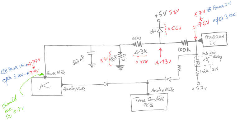
The protection IC is working fine - giving a low output signal after a few seconds of start-up as per manual. The low signal triggers the output relay. This signal is also passed to the controller through the circuitry shown in figure at the power-mute input of the controller.
The power-mute signal should be approximately 0.7v according to the manual but after start-up delay the power-mute signal goes from 4.77v to 3.9v.
I have drawn the schematic of the section I think is relevant (measurements in red). Any ideas as to what's wrong would be really appreciated...
The power-amp section is working fine if given signal from external pre-amp.
According to the manual the unit starts-up in protection mode, if no problem feedback is received by the controller for a few seconds, audio-mute is removed and the controller passes the pre-amp signal to power-amp.
The protection IC is working fine - giving a low output signal after a few seconds of start-up as per manual. The low signal triggers the output relay. This signal is also passed to the controller through the circuitry shown in figure at the power-mute input of the controller.
The power-mute signal should be approximately 0.7v according to the manual but after start-up delay the power-mute signal goes from 4.77v to 3.9v.
I have drawn the schematic of the section I think is relevant (measurements in red). Any ideas as to what's wrong would be really appreciated...
Is it possible D511 has been removed and then inserted incorrectly?
D511 should not be conducting with a 0.66v drop in reverse direction.
Maybe D511 is damaged.
D511 should not be conducting with a 0.66v drop in reverse direction.
Maybe D511 is damaged.
According to your diagram, current must be flowing thorough D511 although it should be reverse biased.
The unit does not seem to be serviced at all.
My suspicion is also pointing to the diode...
One reason for diode in reverse bias could be to absorb current when protection IC output is floating at ~57v initially, so that 57V is not passed to the controller pin.
I could try to replace the diode anyway if I don't get any other clue.
Also, I was thinking, how about adding a 100k pull-down resistor to the controller's Power-Mute pin to see if the unit comes out of protection mode. Advisable?
If the power amp works with another source at pre-in, I would suspect the +/-18V circuit. (if it was in protection mode, the speaker-relay wouldn't be engaged and power indicator would be flashing green.)
The +/-18V circuit is located near the speaker-relay. Easy to find since these transistors gets hot and scorches the PCB to a brownish colour.
Check the voltages at CN24.
Pin 1 should be +18V.
Pin 2 should be -18V.
Pin 3 is ground.
Pin 4 is power mute.
If either pin 1 or 2 has the wrong voltages, no OP-amp in the receiver will work and the only sound you'll get is some random static.
If this is the case, resolder every pin on transistors Q206-211.
The power indicator is flashing. I will check the rest though.
In any case Power-Mute pin on the controller should be at around 0.7v.
In any case Power-Mute pin on the controller should be at around 0.7v.
OK.
I measured the voltages over D511 on a TA-2E , (different model, same circuit tho.), on power on it started at 0.5V and when the speaker-relay engaged it rose to 5.4V.
Voltage over R573 starts at 1.2V and then drops to 25mV.
Voltage over R5113 starts at 4.8V and then drops to 0.14V.
Voltage on power-mute pin starts at 4.9V and drops to 0.15V.
I'd suspect a bad solder on the power-mute pin or defective IC given your measurements.
You can test disconnecting CN-1 on the controller board, thus disabling the power mute and it should start playing again. (it also disables the green flashing during power on.)
Controller needs a low on Power-Mute pin for the LED flashing to stop, how will disconnecting CN1 help? How will the pre-amp start working?
Also, CN1 contains Power-Off signal, are you sure I should try to disconnect CN1..
Also, CN1 contains Power-Off signal, are you sure I should try to disconnect CN1..
Forget about disconnecting CN-1, it shouldn't make any difference on your unit, I had a brain-fart.
Besides, what is the voltage on pin 1 on CN-11, "out mute" pin 14 on U503.
Should be ~5V at power on and should drop to a few mV after speaker-relay engages.
Should be ~5V at power on and should drop to a few mV after speaker-relay engages.
I disconnected the U503's Power-Mute pin (cut one jumper) and guess what! everything is now normal!
The pin is floating at about 1.5v though..
The pin is floating at about 1.5v though..
There are 3 jumpers next to D514. I cut center one. It basically disconnects pin 7 from the rest of the circuit.
Would be nice if most of the discussion had some relevance to others. I have no idea
what the pin, connector and IC numbers signify ?
Is Pass Labs related to this unit ?
what the pin, connector and IC numbers signify ?
Is Pass Labs related to this unit ?
The pre-amp and power amp section of the Nakamichi TA-3 was designed by Nelson Pass (Stasis). Nakamichi used Stasis under license from Threshold/Pass.
The references to components are from the Service manual of TA-3. Since the product is long discontinued & Nakamichi closed, this thread should of some help to someone having the same problem with the TA series of recievers.
The references to components are from the Service manual of TA-3. Since the product is long discontinued & Nakamichi closed, this thread should of some help to someone having the same problem with the TA series of recievers.
You did rule out bad solder on pin 7 or a damaged circuit trace?
And maybe a far fetched idea.
It might be the reset circuit that isn't working properly.
U503 is a microcomputer and if it isn't reset during power on, noise from the power supply might cause it to not work properly.
And if I understand it correctly, C408 and Q405 (placed on the PSU board) will during power on cause a "LOW" on the reset of U503 (pin 45) and for all I know, reboot it.
Dunno if I makes any sense 😱
- Status
- Not open for further replies.
- Home
- Amplifiers
- Pass Labs
- Help: Nakamichi TA-3 Stasis Receiver