1. Is this tear repairable? If so how?
2. Why does the cone look wet around the edges
3. How do i clean the dirt off the speaker.
4. Are those tweeters even real?
5. The tweeters seem to be hooked up directly in parallel with the speaker. Is this okay or the resistor i found goes in somewhere.
Any help will be highly appreciated
2. Why does the cone look wet around the edges
3. How do i clean the dirt off the speaker.
4. Are those tweeters even real?
5. The tweeters seem to be hooked up directly in parallel with the speaker. Is this okay or the resistor i found goes in somewhere.
Any help will be highly appreciated
Attachments


Welcome to the forum!
Repair the tear with tissue paper and slightly watered down PVA adhesive.
The tweeters are piezo types which usually have a resistor in series with them.
The cone surround has been doped during manufacture to strengthen it so looks darker than the rest of the cone.
Brush any loose dirt off the cone, but don't wet it.
P.S. A piezo tweeter can be connected directly across the bass speaker terminals, but putting a resistor of the order of 20 ohm in series with the tweeter makes it a more stable load for the amplifier.
Do i need to factor in the tweeter and the resistor while choosing the amplifier? How do i do that?
The 2415 257 48008 is a fullrange driver used as OEM driver in tv's from other brands. It's close to the AD 7062/M in specs. It goes back to the 1970's and was made in the Philips factory in Dendermonde, Belgium (now an independent OEM builder called Permium Audio Solutions). It was also used in some japanese cars of that time. The old mid 70's Siemens TV my parents had had that driver btw...
The tweeter i don't know.
The tweeter i don't know.

i found this resistor with it seems to be of about 220 ohms but is clearly not a wire wound one much less one of significant wattage so is that fine? or should i put in a wire wound one?No, but best to include the resistor - a 5 or 10 W wirewound resistor is suitable.
Attachments

From online calculators, i have worked out that i need around 1 cubic feet of enclosure volume. are my calculations correct?
i would also like some amplifier module suggestions and lastly how long/wide should i make the bass tube and can i make it out of a pvc pipe?
i would also like some amplifier module suggestions and lastly how long/wide should i make the bass tube and can i make it out of a pvc pipe?
These drivers are much older than me then. My father says he got these from some neighbour who was moving and had no space left for these so he just gave them away. It had an amp with it but it seems that kid me broke it by messing with the knobs. I have taken upon myself to revive them and finally fix my 'messup'. Anyways it feels like its gonna be fun.The 2415 257 48008 is a fullrange driver used as OEM driver in tv's from other brands. It's close to the AD 7062/M in specs. It goes back to the 1970's and was made in the Philips factory in Dendermonde, Belgium (now an independent OEM builder called Permium Audio Solutions). It was also used in some japanese cars of that time. The old mid 70's Siemens TV my parents had had that driver btw...
The tweeter i don't know.
should i put in a wire wound one?
For certain, yes!
Use a standard value of 22 ohm and make sure it's a 5 W or 10 W ceramic (wirewound) resistor.
From online calculators, i have worked out that i need around 1 cubic feet of enclosure volume. are my calculations correct?
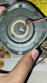
The Philips driver has the trademark octagonal basket and a paper/fabric surround.
Am I correct in assuming that the diameter of the cone is 7 inches and the corner to corner measurement is 8 inches?
Such drivers were designed to work in 25 litre (0.9 cu ft) sealed enclosures loosely filled with absorbent material.
I would try sealed rather than ported. You can't calculate port dimensions unless you know all the necessary parameters of the driver.
As far as choice of amplifier module is concerned, perhaps a TPA3116 based amp like this one:
https://www.ebay.co.uk/itm/20420736...s=ispr=1&amdata=enc:1hCqT9fUGT_GXV_rKDu5ZxQ73
I don't know whether I'd go that far but I'd measure this resistor before reusing it, or in at least investigating whether it may have been sufficiently specified to begin with if replacing it.should i put in a wire wound one?
More importantly, where was it used? You might have a little testing to do before making a decision.
I'd measure this resistor before reusing it, or in at least investigating whether it may have been sufficiently specified to begin with if replacing it.
Srimp has said that the resistor is 220 ohm and, judging by the second photograph in post #1, it is rated at no more than 1/4 of a watt.
I think it may simply be a rogue resistor!
220 ohm is inappropriate for the desired application, as that would roll down the high frequencies noticeably. Instead, I have recommended 22 ohms in series with the piezo. It does not have to be a wirewound resistor, but a power handling measured in watts is preferable to one measured in fractions of a watt.
If Srimp wanted to get the best performance from his piezo tweeter, he could wire the 22 ohm resistor in parallel with the tweeter and connect a 4.7 uF film capacitor in series with the parallel tweeter/resistor combination.
Srimp said he found the tiny resistor with the drivers and asked if it should go in somewhere.
The resistor is not included in the wiring shown in Srimp's photographs, but is only pictured as a separate entity.
It's possible that it may have nothing to do with the speakers at all, and has simply "fallen in the box"!
The resistor is not included in the wiring shown in Srimp's photographs, but is only pictured as a separate entity.
It's possible that it may have nothing to do with the speakers at all, and has simply "fallen in the box"!
As you said, and I don't disagree. A resistor will roll off the highs into a capacitive load, and always with the same slope. It only makes sense as a series element in a subset of possibilities.
There was a Philips factory in Pune (formerly called Poona), where they made speakers, till about 20 years back.
The best speakers in India, proper factory, good quality paper, coil, magnet and rubber.
Part numbers may be same as from other Philips factories.
They also had plants for metal stamping, and plastic injection molding in Pune.
As for amplifier, I use Philips Powerhouse (2 cassette / radio / aux / CD in) as they are very well made, got them in flea market...
Japanese driver chips, Japanese and Philips caps, heavy linear power supply.
If you want to build, many sellers are there in India.
For a first build I would recommend a ready plate amplifier, with 15-20 watts output, based on the many chips sold like 2030 and 4440, decent but not ultra sound quality, enough for home use.
Speakers can be reconed for about 100 Rupees each in most cities, that is an option, but better try and keep the cones original unless badly damaged, or magnet off center.
I have many Philips speakers, tweeter was through a small 4.7 electrolytic, nothing else in crossover, no stuffing, just 3/8" particle (chip) board box. And a full range main driver.
Last edited:
Can you tell me how the tweeter is wired in similar speakers? In series, parallel and what would be its approx resistance.I have many Philips speakers, tweeter was through a small 4.7 electrolytic, nothing else in crossover, no stuffing, just 3/8" particle (chip) board box. And a full range main driver.
Tweeter fed in parallel from main driver through a capacitor in series with it.
Try and get a plate amp with Keltron capacitors, slightly more expensive than those with Chinese capacitors, much more reliable.
Try and get a plate amp with Keltron capacitors, slightly more expensive than those with Chinese capacitors, much more reliable.
The resistance of a piezo will effectively be so high that you'd call it infinite. On the other hand they will present as capacitive so their impedance falls with frequency. Usually piezos have a relatively high impedance.
- Home
- Loudspeakers
- Full Range
- Help repairing old Philips speakers