
lets say the valve is a 12au7 , how would the 9 pin connections from the valve fit into this diagram
For many small dual triodes, including the 12AU7,
http://www.tubebooks.org/tubedata/RC30.pdf
First section (channel A)
plate=1
grid=2
cathode=3
Second section (channel B)
plate=6
grid=7
cathode=8
4,5=12V filament
9=filament center tap
You count the pins as seen on the bottom,
clockwise from the gap.
Attachments
Last edited:
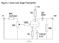
Thanks rayma for your help , but when I look at the valve in the circuit it has
3 terminals and the pot looks like it is connected to the grid , but the valve has 9 terminals , most circuits are drawn like this where they don't show all the terminal connections to the valve , im hoping that the rest is taken for granted if you understand circuit diagrams . phil
3 terminals and the pot looks like it is connected to the grid , but the valve has 9 terminals , most circuits are drawn like this where they don't show all the terminal connections to the valve , im hoping that the rest is taken for granted if you understand circuit diagrams . phil
Thanks rayma for your help , but when I look at the valve in the circuit it has
3 terminals and the pot looks like it is connected to the grid , but the valve has 9 terminals , most circuits are drawn like this where they don't show all the terminal connections to the valve , im hoping that the rest is taken for granted if you understand circuit diagrams . phil
Right, that is not a complete schematic, but it's easier to understand than a complete one.
Here's an example of a complete tube preamp schematic.
Attachments
Last edited:
bellyboo3,
The most simple wiring of a 12AU7 filament is with either a 6.3VAC secondary winding, or a 12.6VAC secondary winding.
AC filaments:
6.3V secondary, one lead goes to pins 4&5, the other lead goes to pin 9.
It is a good idea to connect a 1k resistor from pin 4&5 to ground, and another 1k resistor from pin 9 to ground (as long as the rest of the circuit design permits).
12.6V secondary, one lead goes to pin 4, the other lead goes to pin 5.
If the 12.6V secondary does not have a center tap, and if the rest of the circuit
permits, you can connect pin 9 to ground. Or if the rest of the circuit permits, connect a 1k resistor from pin 4 to ground, and another 1k resistor from pin 5 to ground.
DC filaments (more complex, becuase you need a DC supply):
You need a 6.3VDC connected to pin 4&5, and the other connection to pin 9.
If the rest of the circuit permits, you connect 1k resistors just like the 6.3VAC case above.
Or,
You need 12.6VDC connected to pin 4, and the other connection to pin 5.
If the rest of the circuit permits, you either connect pin 9 to ground, or use 1k resistors the same as in the 12.6VAC case above.
Last edited:
There are two sorts of circuit diagram, abstract ones like this, which show the principle and omit all unnecessary detail, and an actual circuit for construction (which is likely to give part numbers, pins, component values or part numbers.
With valves/tubes its conventional to not show the heater wiring, that's a given.
If you have a dual triode and wish to implement this circuit you simple choose one of the triode sections and use that, not connecting the other.
With valves/tubes its conventional to not show the heater wiring, that's a given.
If you have a dual triode and wish to implement this circuit you simple choose one of the triode sections and use that, not connecting the other.
Thanks guys , basically the picture is from here
(SJS Electroacoustics Home Page - Makers of Arcadia Valve Amplifiers) click on (read it) then line pre
it gives a large choice of valves and the resister values , also the power supply
ecc88 and 6sn7 also up for consideration , I think you would have to use mono pots x2 , also like the look of this board
( 1pcs LITE LS10 tube preamp PCB empty plate base on AUDIO MOTE M7 circuit | eBay
still trying to learn but im good with the soldering . so basically you can run
both triodes or just one . phil.
- Status
- This old topic is closed. If you want to reopen this topic, contact a moderator using the "Report Post" button.
- Home
- Amplifiers
- Tubes / Valves
- Help understanding circuit