I've been looking in to building a SET OTL headphone amp and I want to use the tung sol 6SN7 for the voltage gain and Svetlana 6AS7 as power tubes. B+ is 200V right now but this can be adjusted I just don't want to face any huge issues with the 250V rating of the 6AS7's. the goal is to drive a pair of HD660s with ease and maybe even something with a lower impedance in the future.
I'm facing some issues with the simulation (orcad 2019) it seems like the coupling cap in the first stage is blocking pretty much everything I get roughly 5 uV swing after it even if I have a good 10v swing before it (which is still too high for the bias of the second stage).
Do you guys see any horrible misstakes made?
how can I improve it?
Do I need electrolytic coupling caps in the output stage as well or is it safe with only the poly ones?
also am I adding the negative feedback from the output the correct way, how can I increase it?
Lots of questions I'm still learning my ropes around these circuits.
Attachments

Broskie has a similar design on his tube cad site. I’ll try to find the links.
Cathode-Follower OTL and SIT FETs
Have you bode plotted the design?
Cathode-Follower OTL and SIT FETs
Have you bode plotted the design?
Last edited:
..... it seems like the coupling cap in the first stage is blocking pretty much everything.....
You put a "1M" resistor. Maybe you were thinking "Meg"? No, to most SPICEs "m" or "M" is milli, super small. Spell it out "Meg" and it may work better.
(You might think m is small and M is big. But when SPICE was new we did not always have lower-case characters. And each new SPICE tries to be back-compatible with older models and circuits. So spell-out Meg.)
Attachments

Last edited:
Broskie has a similar design on his tube cad site. I’ll try to find the links.
Cathode-Follower OTL and SIT FETs
Have you bode plotted the design?
it is based on his design but i went with bigger bottle tubes because prettier to look at and hopefully they sound just as good. I will have another look there, i don't think i've read the article you linked yet.
Thank you for that i'm new to the world of spice and designing anything this is actually my first attempt at doing everything from the ground up.
Yes it will be fixed tomorrow, thanks a lot for the pointers!
Yes it will be fixed tomorrow, thanks a lot for the pointers!
Only issue I have is that the NFB circuit and balancing idle current between the tubes.
I was trying to find the tubecad circuit but basically each tube is isolated by the feedback from the output past the output cap.
This means if a tube fails or shots it doesn’t change the parallel tube balance.
Nope I was wrong, I found the link: More OLT Design
I was trying to find the tubecad circuit but basically each tube is isolated by the feedback from the output past the output cap.
This means if a tube fails or shots it doesn’t change the parallel tube balance.
Nope I was wrong, I found the link: More OLT Design
Last edited:
it is based on his design but i went with bigger bottle tubes because prettier to look at and hopefully they sound just as good. I will have another look there, i don't think i've read the article you linked yet.
The 6as7 will have a low output impedance than the ecc99 so you’re going the right direction for lower output impedance with that choice of tube.
You’ll want the fuse the B+ line too.an enhancement is to use a constant current source to replace the cathode resistor. However that will change the sound a little.
Thank you for that i'm new to the world of spice and designing anything this is actually my first attempt at doing everything from the ground up.
Yes it will be fixed tomorrow, thanks a lot for the pointers!
It’s possible todo a bode plot to show the frequency response.
The Input uses AC(1) or whatever the input voltage is peak. Then use a .ac command rather than .trans and the output will the switch to provide you with a frequency sweep and dB response, additionally you can get phase change too. Clicking elsewhere in amp and you will get the bode plot for that wire. So it’s great for narrowing down issues like wrong cap values limiting driver to grid issues (parallel tubes start taking more current due to the miller capacitance of a house grid accumulating).
C1 at 10uF is massive for a sn7 to sn7, perhaps the 1mOhm that PRR pointed to was causing you issues. Likewise you make find a parallel output needs more than 0.1uF. For example I will use a 0.22uF for most things but for a parallel drive of 4 ecc99s I found it needed more and ended up with a 0.22uF and a 1uF in parallel for the coupling caps. Your mileage may vary with that - use the bode plot to see if your calculations match.
One thing you need to do is put the ESR (series resistance) for your chosen caps into the model. That will alter the frequency response.
I use FKP1 PP 630V 400Vac caps the 0.22uF has an ESR of approximately 0.055uF however it depends on the frequency like all caps so I tend to use an average figure. They are stupidly fast with 11,000V/uS - extreme overkill for the 3-20V/uS that most amps are happy with, even when derated.
I also use MKP10 630V 400Vac for the 1uF, the ESR is higher than the PP. Also I use non-polar 50V MUSE caps, IIRC these have an ESR of 0.38. Paralleling caps means a lower ESR should you need to adjust with your cosmetic cap. There is a danger in using the 50V caps as an output cap with a shorted tube but then you’re looking at TVS or crowbars to short B+ to ground to blow the fuse or grip a shutdown before that cathode line gets to 50V.
Lastly output caps. The bode plot may show low frequency roll off with the output caps. 22uF may be a little low, depending on the response curve of your headphones.
To give you and example - for 32/55 ohm HPs man use up to 4700uF capacitance to prevent lower roll off. When looking at the ecc99 version of your amp I have 4x330uF nonpolar + 1x0.22uF per tube. I have that made up and have listen though the bank of caps - it sounds great.
Oh and what input Vpeak are you using? I don’t see any issue with driving the 6as7s but at higher impedance headphones the amplification (lager peak to peak voltage, lower current) will all come from the 6sn7s.
Last edited:
I just noted one thing with the 6as7 - you have fixed biasing. Normally this isn't recommended with the 6as7, with cathode biasing or DC servo in the case of totem pairs for push-pull amps. Now, I don't have experience with the 6as7.
Your current biasing scheme only is operating with only a ground connection. There's a couple of interesting points at this point in Broskie's design (I'm using part of mine initial playing with his ecc99 amp but it's NOT entirely the same as I use a -ve rail):
View attachment 994198
Here I'm using 12bh7a and ecc99s, the 12bh7a are cathode coupled. You'll need to adapt the concepts to your 6sn7+6as7 design if you want to adopt them.
This is basically the Broskie design from the second link, a bit further down the page. However I'll point out some points that you may want to research for your design:
1. The feedback loop is connected to both B+ and ground (C2/R10/R6 etc). This is part of Broskie's Akkido - feeding power supply noise in controlled quantities into the the amp at specific points to cancel out the power supply noise.
2. The use of a 10M resistor to provide the some upward lift for the bias but also IIRC this is partly compensation network (I remember someone suggesting this but it's a little above my pay grade).
3. The LT317As, I was playing with the concept. The reality is that you need -ve to keep them above the 3V drop they require to keep them active. There are plenty of better choices of CCS.
I remember Broskie mentioning the 6as7 likes have a 10ohm cathode resistor to keep the tubes from running away? Someone may be able to comment further on that. My 6as7 design didn't get beyond the drawing board.
In LTSpice you can also check the power dissipation of resistors etc, so you can double check your calculations for selecting the right wattage rating for the resistor.
Also one last point 😉
With the design the tubes are running class A.
3 x 6as7 triodes. Finger in the air - that's 50-60mA idle with 20-50mA swing max. Or 150mA total. Although this depends on the headphones you're using (dBV?), the 150ohm suggests a lower current design with more need for voltage swing. I'd probably expect given Mark's great links: https://www.diyaudio.com/forums/headphone-systems/364344-designing-headphone-amp-17.html#post6782748
An example close to 150ohm would be:
AKG K601 99 131 3.548 27.085
That's 131ohm, requiring 3.5V to drive and 27mA to hit 'loud' levels - 150ohm would require more voltage and less current as an adjustment.
The reason for Broskie paralleling tubes is to reduce output impedance thus reduce frequency rolloff. Just be wary of the volume levels three 6as7s will drive the headphones to 😀.
On the circuit - I would add a 10K resistor to ground on the headphone side in parallel with the headphones. This prevents the capacitors from charging and reduces the pop on inserting headphones. Also putting a 150ohm across the the headphone connections so when the phones are disconnected the resistor makes a load that allows the caps to not charge up too much. When the headphones are inserted the jack disconnects the 150ohm from the circuit.
Sorry that there's no cohesive line of thought in my random posts but as long as you've started at the headphones and worked back - from the headphones you know the V and mA required, that then defines the each state working backwards. Lastly - the negative feedback is a % of the output feed back (including any aikido magic).
Last edited:
Thank you for all tips, i will revisit broskies site and see if i can find more on the 6as7 on there, i wouldnt mind going for a CCS supply for the 6as7's but (there is always a but...). i would like to do it with FETs but i dont have the know how at least not yet and i'm in no rush to get this to the presses i just figured a fixed bias would be good enough to get me going and learning along the way.
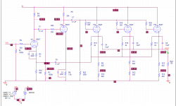
i've made some tweeks in the schematic, mostly in regards to the cap values and got the simulation working as intended as well as the plots you asked for. The response doesn't look to good, it rolls of very early to my eyes.
i was planning on using jantzen superior Z-caps for the output and was hoping i could get by not having any electrolytics on the output but if there is a need for a large capacitance then i just have to make it happend.
Attachments
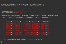


I think you need to look at the bode plot, typically the plot should be flat and then roll of -3dB at the edges as frequency response fall off. What is the input? 6% seems quite high.

I'm no expert but your feedback loop has a .1uF working into a 500 Ohm. You are applying 6dB per octave less feed back under 3200 Hz or so. That won't work
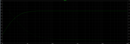
when i try to plot the DB of i get the plot with the big hump around 30hz then the sharp roll off. it is the NF that is the cause of it not completly sure why.
I would get the non-feedback frequency response good first then work on the feedback. What does the plot give you without feedback?
Each capacitance and resistance resulting in low and high filters. What you’re seeing is the result of the at filtering. Having negative feedback can hide a mutltitudes of sins.
Personally I would look at 0.22uF (0.055ohm ESR) in the coupling caps without NFB initially. There is a lot of capacitance in paralleling tubes so that current charge needs to flow through to the grids
Last edited:
Sorry for the silence
I'm sorry for the silence, i decided to go back and do some more reading and research before i continue posting the development here.
i have made some changes, i decided to get rid of the second 6SN7 that was intended to be used for voltage gain in favour of eliminating global NFB.
the 3 6AS7 for output is still in my scope but for simulation and testing i only have 1 currently drawn up.
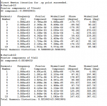
i also decided to add CCS to the different stages which gave me some strange results and a small headache. the cascaded one over the 6SN7 ended up yielding a enormous voltage amplification (3vPeak in to 60 vPeak out) which seems a lot for a single tube with a mu of 20... other then that it works perfectly with a 4mA bias.
When it comes to the 6AS7 it's a different story, i struggle to get the cascade CCS to give me a 50mA bias so i ended up going to a single FET but to no prevail. adding more upper FETs in parallel doesn't seem to change anything either. i did succeed in getting good results by paralleling a bunch of CCS networks (200-250mW into 300Ohm @ 1.2%THD) but something tells me that having 5-6 parallel networks will decrease the impedance the tube/s sees.
From what i've read i don't want to give up on the idea of having a cascade CCS for the 6AS7s but unfortunately i'm out of ideas and need some help here or pointers to any good resources for information.
Any suggestions of good articles or maybe a good DN2540 model?
I'm sorry for the silence, i decided to go back and do some more reading and research before i continue posting the development here.
i have made some changes, i decided to get rid of the second 6SN7 that was intended to be used for voltage gain in favour of eliminating global NFB.
the 3 6AS7 for output is still in my scope but for simulation and testing i only have 1 currently drawn up.
i also decided to add CCS to the different stages which gave me some strange results and a small headache. the cascaded one over the 6SN7 ended up yielding a enormous voltage amplification (3vPeak in to 60 vPeak out) which seems a lot for a single tube with a mu of 20... other then that it works perfectly with a 4mA bias.
When it comes to the 6AS7 it's a different story, i struggle to get the cascade CCS to give me a 50mA bias so i ended up going to a single FET but to no prevail. adding more upper FETs in parallel doesn't seem to change anything either. i did succeed in getting good results by paralleling a bunch of CCS networks (200-250mW into 300Ohm @ 1.2%THD) but something tells me that having 5-6 parallel networks will decrease the impedance the tube/s sees.
From what i've read i don't want to give up on the idea of having a cascade CCS for the 6AS7s but unfortunately i'm out of ideas and need some help here or pointers to any good resources for information.
Any suggestions of good articles or maybe a good DN2540 model?
Attachments

- Home
- Amplifiers
- Tubes / Valves
- Help wanted - SET OTL Headphone amp