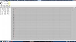
I just started using PSUD2 for the first time and I'm trying to model a LCLC filter for a line stage amp. I've got a 700VCT transformer, I'm looking for around 300V B+ and my circuit will draw around 37mA. Could you guys take a look at the attached simulation and let me know if this looks OK?
Is the initial ringing a problem? It levels out after a few seconds.
How is delay used in the simulation? I left it at 0.
Is the initial ringing a problem? It levels out after a few seconds.
How is delay used in the simulation? I left it at 0.
Attachments
My circuit is designed to operate with around 300V B+. I have either a 700VCT or a 760VCT power transformer to choose from on hand. For chokes I have a 12H 150ohm 150mA, a 10H 80ohm 200mA, and a 2H 29ohm 200mA. The 12H is a vintage potted Chicago I intended to use as the input choke. For the caps I've got a 200uF 600V film cap I want to use - I assume it would be best used as the final cap? I've also got a 70uF and 30uF film cap, or a bunch of higher value electrolytic caps I wanted to avoid in this build.
How can I make it would with minimal additional parts?
How can I make it would with minimal additional parts?
> I have a 12H 150ohm 150mA, a 10H 80ohm 200mA, and a 2H 29ohm 200mA.
But your simulation shows milli-Ohms.
Which is just not reasonable for a dozen-Ohm choke. Put the right values in and run it again.
A 5U4 is a Big Amp bottle. This ~~30mA load is well within the ability of the smaller cheaper 5Y3.
Use "delay" to see just what you get *while you are listening*. (You don't listen immediately after switch-on; and the actual start of a hot-cathode rectifier is not easily simulated.) This also eliminates the numbers starting from zero volts, skewing the "diff" number. Using a several-second delay, I get 8 milli-Volt "diff", which is peak-to-peak ripple, a number you apply to the amplifier's PSRR to figure output ripple.
Oops! Thanks for catching that. Attached is the same simulation with the corrected choke DCRs. This looks more like what I expected.
I'm running split rails after the rectifier, so the 5U4 will be seeing about a 70mA load. I didn't think PSUD2 could model split rails so I just input the data for one side. I know 70mA is still in 5Y3 territory but I've already built several amps with 6087 rectifiers, and preamps with 6087 and EZ81 rectifiers - I've been itching to use a large bottle rectifier! The other thing I wanted to try was a choke input power supply filter. I've used CLC filters in all my other tube amp builds.
So I'm at around 290V B+, which should be fine. Alternatively I could use the 760VCT transformer and add an additional RC node at the end to bring the voltage down to 300V. A 400R should do it. Ripple would be puny and defeated.
Attachments
- Status
- Not open for further replies.
- Home
- Amplifiers
- Power Supplies
- Help with LCLC Filter in PSUD2


