Hello,
Currenly working on my Hifonics BXI6000d.
Maybe someone can helpme with this.
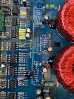
Someone was working on this pcb, and i think he soldered the wires from the feedback resistor on the wrong spot.
Looked at many pics of the two wires. But can't see clearly where its connected to..
Is it connected on both rails on the Drain (center pin)

Currenly working on my Hifonics BXI6000d.
Maybe someone can helpme with this.
Someone was working on this pcb, and i think he soldered the wires from the feedback resistor on the wrong spot.
Looked at many pics of the two wires. But can't see clearly where its connected to..
Is it connected on both rails on the Drain (center pin)
It's supposed to be connected between the drain of the 'low'-side output FETs to the 1 ohm resistor.
Thanks Perry,
So if i understand well, both wires coming from de 1 ohm resistor should be on both banks connected to the centerpin of the FQA38N30 (Drain) correct!
So if i understand well, both wires coming from de 1 ohm resistor should be on both banks connected to the centerpin of the FQA38N30 (Drain) correct!
The wire connects the rail-rail waveform of each bank to the resistor. The connection is to the high-side source terminal which is also the low-side drain.
Looking at photos online, it appears that they cut a trace on the top of the board and re-routed the signal from another point. I have no photos (of my own) of the top of this amp so I don't know if this trace cut is common to other revisions.
Looking at photos online, it appears that they cut a trace on the top of the board and re-routed the signal from another point. I have no photos (of my own) of the top of this amp so I don't know if this trace cut is common to other revisions.
I don't know why this has been modified. It seems a factory upgrade. Seen other pics of the BXI6000D Hifonics with the same modification..The wire connects the rail-rail waveform of each bank to the resistor. The connection is to the high-side source terminal which is also the low-side drain.
Looking at photos online, it appears that they cut a trace on the top of the board and re-routed the signal from another point. I have no photos (of my own) of the top of this amp so I don't know if this trace cut is common to other revisions.
But still don't know where to connect the other wire to.. One pic again. Of one side i know where it should be, cause is wasn't soldered yet. Is there a schematic around that show how the feedback is connected..
Attachments

Both serve the same purpose (but for different 21844s). They both connect to the low-side drain terminal.
Thanks Perry, now i know what theybhave done wrong. One side they soldered it to the Gate. Checked allready the powersupply. Starts up fine. But have to change the 21844's right channel makes a short. And don't trust the left. Thanks for the info Perry..
Yes, now it's clear for me.. Thanks again Perry.
As soon as the parts arrive, i'll start to replace them..
Can i check the signal, with a 50Hz input without the fets inside the board..?
As soon as the parts arrive, i'll start to replace them..
Can i check the signal, with a 50Hz input without the fets inside the board..?
If you drive a signal into the amp, you can check the signal up to the input of the 21844. If the 21844s are defective, that's as far as you can check, at this point.
Ok thanks.. i already desoldered the driver pcb v2 out of the amp. And Checked the resistance of the output. On de Right i meassure a short. Left channel looks ok. Don't want to take any risk on blowing up my New fets. I'll be carefull before powering up. And cross my Fingers 😀. If theres gonne be smoke, the current must be high enough! Thanks for the advice again Perry. Let you know how its works out for me.. even bought a waveform generator for this project..
Yes, but desoldered it this evening. And saw that pin 3 and 5 are bridged on the board. On the bench , i meassured a short between pin 5 and 6 of the 21844. So the Lo is shorted. Other 21844 is fine. No shorts. But gonna replace them both anyway. Tested the rest of the component on the pcb. These are ok.
The 12v regulators often get damaged so confirm that those are within tolerance before installing the new ICs.
The high-side B+ capacitor and diode often fail, as well.
Do you have a low-voltage split supply that you could use instead of full rail voltage?
If one 21844 did survive, and some of the original output transistors, you could use those to confirm the function of the rest of the components. The output inductors sometimes have intermittent shorts.
- Home
- General Interest
- Car Audio
- Hifonics BXI 6000D wire location