Hello everyone!
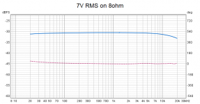
I have been doing some bandwidth measurements on a SE prototype amp, and I can see a decrease of the output voltage at higher frequencies, reaching -2.5dB at 20Khz (pure resistive load):
I have checked the levels at g1 of the output tubes, varies very little:
1Khz: 106Vpp
20Khz: 103Vpp
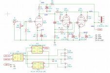
The only think left is the output transformer, which is from Aliexpress. Should I assume most of the high frequency roll-off is happening due to the output transformer? The amp is not using global negative feedback, below the schematic for reference.
Link to the output transformer: https://www.aliexpress.com/item/4000899015634.html?spm=a2g0o.order_list.0.0.367c18020HinhR
Thank you!
I have been doing some bandwidth measurements on a SE prototype amp, and I can see a decrease of the output voltage at higher frequencies, reaching -2.5dB at 20Khz (pure resistive load):

I have checked the levels at g1 of the output tubes, varies very little:
1Khz: 106Vpp
20Khz: 103Vpp
The only think left is the output transformer, which is from Aliexpress. Should I assume most of the high frequency roll-off is happening due to the output transformer? The amp is not using global negative feedback, below the schematic for reference.

Link to the output transformer: https://www.aliexpress.com/item/4000899015634.html?spm=a2g0o.order_list.0.0.367c18020HinhR
Thank you!
I would say it is perfectly normal. Can you hear it?
I agree. That's actually a pretty good response plot for an SE amp with a $30 output transformer. Feedback might help, or it might just make the amp sound worse.
To be honest, no, I cannot hear it. Playing real music sounds great, especially the voices. Hight sound clean.I would say it is perfectly normal. Can you hear it?
I have not a lot of experience doing such measurements, maybe this is fine.
I expected a lot worse at low frequencies for such cheap transformers. I've been pleasantly surprised, you are right, for $30 is not bad at all.I agree. That's actually a pretty good response plot for an SE amp with a $30 output transformer. Feedback might help, or it might just make the amp sound worse.
One of the goals I had was to build the prototype without gNF to see how low can I get the distortion figures. Not that I have anything against gNF, just interesting.
Good point, and thank you for the hint about the cap, because my oscilloscope probes are only rated for 300V. The cap solves that.You could repeat the measurement on the primary of the xformer. That will tell you how the xformer performs.
(Anode U3a but use a coupling cap!).
Jan
The phase is "too good".The amp is not using global negative feedback, below the schematic for reference.
Try to -temporarily- remove R13 (Schade feedback) and measure it again.
The OPT will deliver on what was promised: 30..20kHz (I suppose -3dB).
You are right, even for a prototype is better not to take any chances. Right now is grounded by the divider used to reduce the output signal, but I will ground it properly, thanks!Ground the output transformer secondary common, it is dangerous to be floating.
It does look too good, you are right. But that's what I get from REW and a Focusrite Scarlett Solo. The amp's output signal goes to the line input via a 10:1 divider, and using the line output as a generator connected to the amplifier.The phase is "too good".
Try to -temporarily- remove R13 (Schade feedback) and measure it again.
The OPT will deliver on what was promised: 30..20kHz (I suppose -3dB).
I will do some more measurements, probably tomorrow.
And removing the feedback resistor R13 will reduce the bandwidth further, perfectly normal.You are right, even for a prototype is better not to take any chances. Right now is grounded by the divider used to reduce the output signal, but I will ground it properly, thanks!
Your amplifier is doing very well!
Enjoy listening to it.
Unless the below factors are met, you will not hear 15 kHz, or 20 kHz, no matter what amplifier you use:
1. The tweeter axis are pointed directly to your ears (both vertically and horizontally). If the speakers are at some distance from your ears, extreme high frequencies are attenuated more versus distance than low frequencies are attenuated versus distance.
2. The recording or signal actually has high frequency content (musical instruments played at very high fundamental frequencies and that is rich in harmonics; test tones from CDs, Test LPs, and signal generators; or highly distorted recordings that either intentionally or by poor production methods create upper harmonics).
3. You overdrive your amplifier into hard clipping (that generates lots of very high harmonic frequencies).
4. You have excellent hearing. Do not play your recordings so loud that you can hear those very high frequency harmonics.
Upper harmonics amplitudes are already very low, versus the amplitudes of the lower harmonics and the fundamental music tones.
If you do continually play the recordings that loud, you soon will not have excellent hearing.
Just my opinions.
Last edited:
Thank you! I definitely like the way it sounds, and that's the ultimate measurement for me.Your amplifier is doing very well!
Enjoy listening to it.
Unless the below factors are met, you will not hear 15 kHz, or 20 kHz, no matter what amplifier you use:
1. The tweeter axis are pointed directly to your ears (both vertically and horizontally). If the speakers are at some distance from your ears, extreme high frequencies are attenuated more versus distance than low frequencies are attenuated versus distance.
2. The recording or signal actually has high frequency content (musical instruments played at very high fundamental frequencies and that is rich in harmonics; test tones from CDs, Test LPs, and signal generators; or highly distorted recordings that either intentionally or by poor production methods create upper harmonics).
3. You overdrive your amplifier into hard clipping (that generates lots of very high harmonic frequencies).
4. You have excellent hearing. Do not play your recordings so loud that you can hear those very high frequency harmonics.
Upper harmonics amplitudes are already very low, versus the amplitudes of the lower harmonics and the fundamental music tones.
If you do continually play the recordings that loud, you soon will not have excellent hearing.
Just my opinions.
It took a bit longer to try this, life gets on the way sometimes 🙂The phase is "too good".
Try to -temporarily- remove R13 (Schade feedback) and measure it again.
The OPT will deliver on what was promised: 30..20kHz (I suppose -3dB).
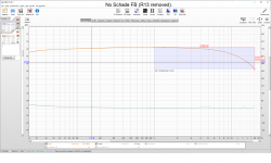
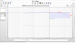
I measured again, with and without R13. The bandwidth got a little worse, as expected, from -2.6 dBF at 20Khz with R13 in place to -3.0 dBF with R13 removed. The surprising thing is that after removing R13, the distortion went down from around 1.1% at 10W to 0.7%. Any ideas why? I used 2Megs based on LTSpice simulations, seems to be of not much help in practice, at least for this circuit. I'm a bit surprised at the distortion figure, after removing R13 there is no feedback in the circuit.
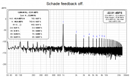
Last edited:
I measured again, with and without R13...
...The bandwidth got a little worse, as expected, from -2.6 dBF at 20Khz with R13 in place to -3.0 dBF with R13 removed. The surprising thing is that after removing R13, the distortion went down from around 1.1% at 10W to 0.7%. Any ideas why? I used 2Megs based on LTSpice simulations, seems to be of not much help in practice, at least for this circuit. I'm a bit surprised at the distortion figure, after removing R13 there is no feedback in the circuit.
That kind of plate-to-grid feedback is best done using pentodes, and the driver stage should have plenty of transconductance too.
It could be that adding R13 is causing U1B to distort too much trying to drive the feedback loop.
Also, the rp of U1B is fairly low (maybe 10k ohms?), which is the series resistance in the voltage divider that defines the amount of negative feedback to the output tubes. Since the output tubes are wired in triode, they don't have much gain, so they'll need more drive from U1B than they would if they were used as pentodes.
I'll bet the amp sounds better with R13 removed.
Perhaps you could try R13 to apply NFB to the cathode of U1B. You would remove C1 from U1B, then connect R13 to the cathode of U1B with a DC blocking capacitor in series between R13 and the cathode of U1B. That will reduce the gain quite a bit, though, and you may have to redesign everything to compensate. But it's another way of applying NFB that might be friendlier to an all-triode amp like yours.
Just an idea to play around with. I'll bet someone will dive in with a better idea.
Maybe connect U2A and U3A cathodes to the OPT secondary for cathode feedback around the output stage?
It my experience that a measurable roll off of frequencies such as you note is almost universally preferred by listeners - at least initially. Extended high frequency can run into ringing problems which are much more objectionable than a slight roll off. its part of that historic tube sound that so many people are looking for.
Shoog
Shoog
I simulated the cathodes to the secondary a while ago, it seemed to work OK for pentodes, but not for triodes, I did not see any significant improvement. The other option about removing C1 will result in a very low gain, I will need an extra stage, which is not desirable.That kind of plate-to-grid feedback is best done using pentodes, and the driver stage should have plenty of transconductance too.
It could be that adding R13 is causing U1B to distort too much trying to drive the feedback loop.
Also, the rp of U1B is fairly low (maybe 10k ohms?), which is the series resistance in the voltage divider that defines the amount of negative feedback to the output tubes. Since the output tubes are wired in triode, they don't have much gain, so they'll need more drive from U1B than they would if they were used as pentodes.
I'll bet the amp sounds better with R13 removed.
Perhaps you could try R13 to apply NFB to the cathode of U1B. You would remove C1 from U1B, then connect R13 to the cathode of U1B with a DC blocking capacitor in series between R13 and the cathode of U1B. That will reduce the gain quite a bit, though, and you may have to redesign everything to compensate. But it's another way of applying NFB that might be friendlier to an all-triode amp like yours.
View attachment 1052219
Just an idea to play around with. I'll bet someone will dive in with a better idea.
Maybe connect U2A and U3A cathodes to the OPT secondary for cathode feedback around the output stage?
I will try though, at least to se what happens, thanks for the advice!
- Home
- Amplifiers
- Tubes / Valves
- High frequency roll-off