Hi everyone,
I am about to start a speaker project using two kicker l7 12 and i am asking for some help.My gold for this project is high spl from 35Hz to 100hz.The space i have is a bit tight, it's 42x18x14. l am interested in any design that can produce more output and cone control than a port box.
L7 spec
dual 4ohms
Revc= 6.850 Ohm
Fo= 33.672 Hz
Sd= 57.615m M²
Krm= 31.109m Ohm
Erm= 0.779
Kxm= 183.096m H
Exm= 0.634
Vas= 47.086 Ltr
Cms= 99.892u M/N
Mmd= 215.695 g
Mms= 223.647 g
BL= 23.126 T·M
Qms= 9.220
Qes= 0.606
Qts= 0.569
No= 0.287 %
SPLo= 86.595 dB
wattage 750rms
xmax 14.1mm
Thanks
Last edited:
More output = ported box.
More control = closed box.
More output+more control+42x18x14 box = impossible
More control = closed box.
More output+more control+42x18x14 box = impossible
Last edited:
I did something like this a couple of years ago for my Cavalier with a couple of L7s. Space was obviously very limited and I'm not sure if these were my final design but it ended up a lot like this. It worked really well and a primary goal for this design was very low port compression, IIRC it was 10 m/s port velocity at full tilt (amp max output). I don't have time to find my old files or resim this, but this gives an idea of what is possible. I think this sim was limited to the amp output power (1250w) so it probably had a bit left in the tank before hitting xmax, but again, I don't really remember. Also, L7 specs changed considerably over the years, mine were 2006 version.
An externally hosted image should be here but it was not working when we last tested it.
An externally hosted image should be here but it was not working when we last tested it.
A tech at kickers confirm that my L7 12's are the 2011 model and the specs in my first post is for the 2011 model.
PPSL Bandpass Design
Beat Street,
Good to see you post this as a general question for all to help you. I see that JAG has already given you something to think about. As I suggested to you earlier, you may want to consider something similar to what Tb46 and I designed for Lawbidng here: http://www.diyaudio.com/forums/subwoofers/264737-pp-slot-loaded-sub-alpine-swr-12d2.html
It would look something like this:
For the Kicker driver instead of the Alpine, the box is going to have to be quite a bit bigger. It may be right on the edge with what you have specified as your limit. It's hard to tell until a good drawing is made in CAD. To first, order, I think it may work.
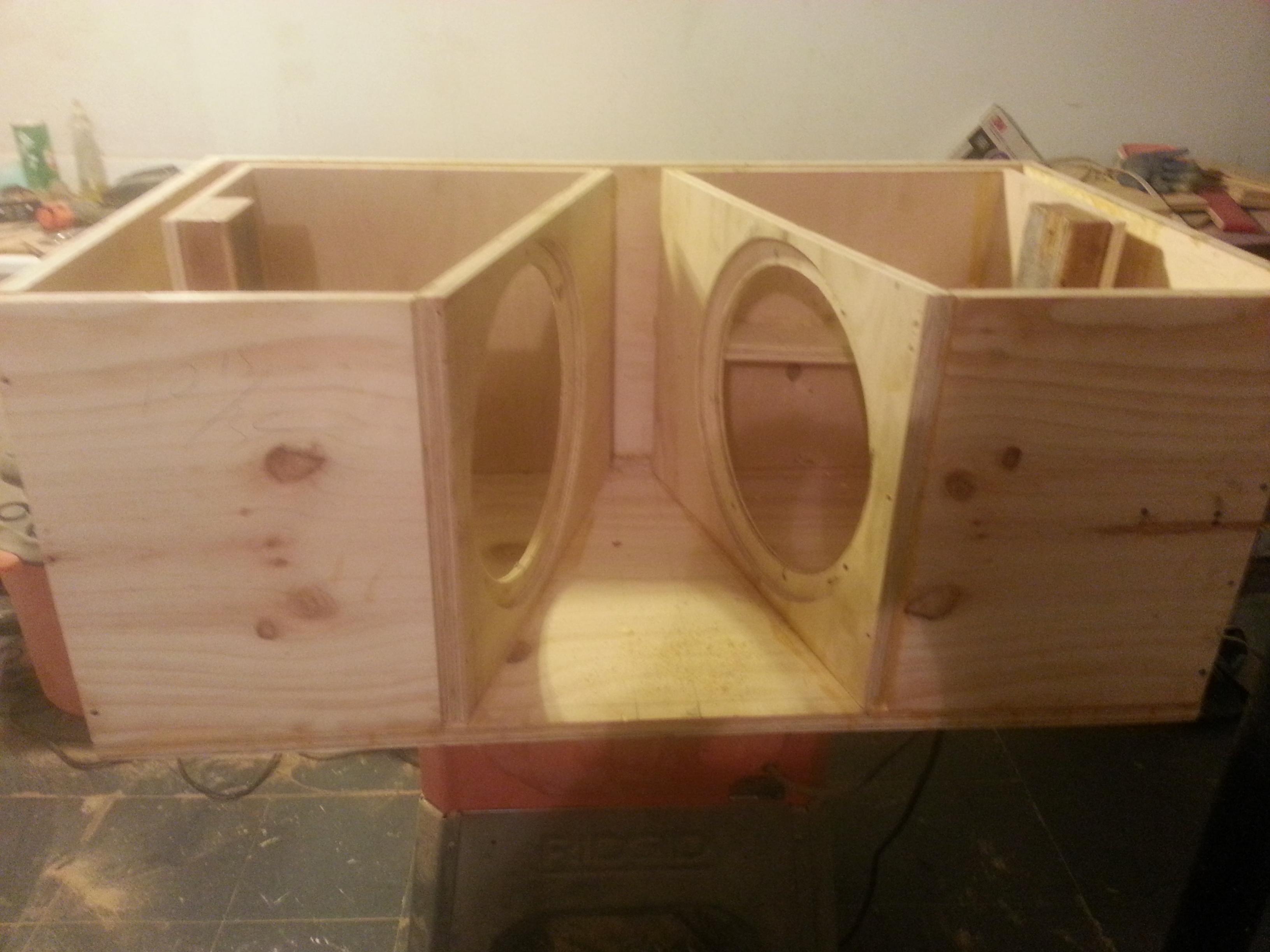
My design uses two 75 liter chambers and the drivers are mounted on the walls of the V exit slot in push pull mode to reduce distortion from suspension asymmetry, but more importantly, make it much easier to mount the drivers than a straight channel. Each box is 14 in tall internally with a wrap around vent that is 1.5in wide x 14in tall x 30in long. The V slot is 3in wide at the throat and 12in wide at the mouth and 15in deep axially. I could re-run the sim with a 12.5in tall V slot so that your true external height if using 3/4n ply will be 14in. Not hard to do but lets see if you like the results here.
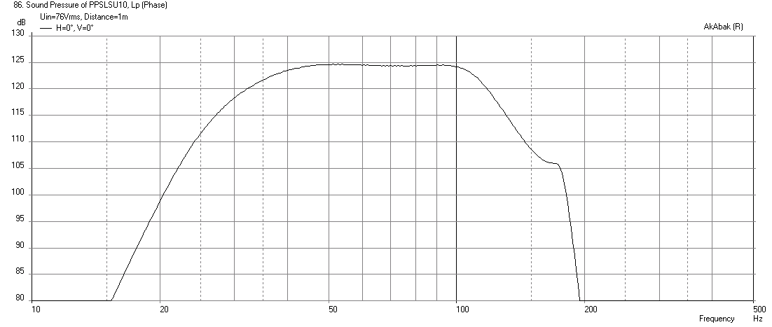
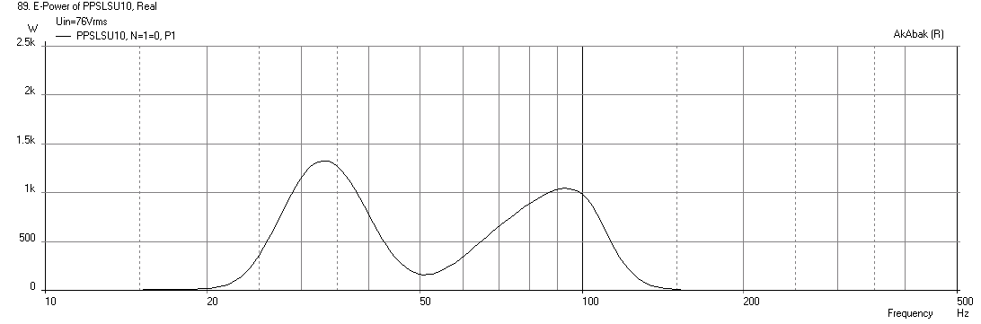
Sims are for 2pi space, max SPL is 124.6dB at 76 volts rms with a -24dB/oct high pass filter at 26Hz, and bass extension is 34.8Hz at -3dB point. Response appears to be very flat up past 100Hz. Max electrical input is 1.33kW which is below the 1500watt limit with two drivers. I believe this meets your specs.
Max SPL at 76 volts rms, here with -48dB/oct LPF at 110Hz:
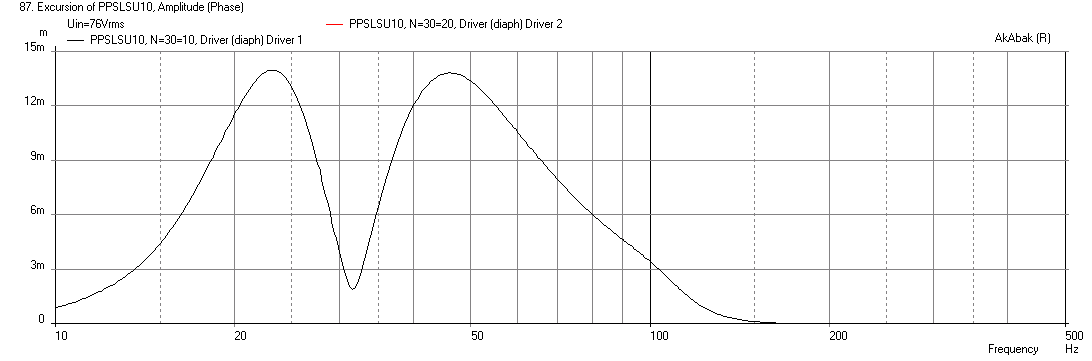
Cone displacement at 76 volts rms:
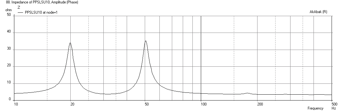
Impedance:
Electrical power input:
Beat Street,
Good to see you post this as a general question for all to help you. I see that JAG has already given you something to think about. As I suggested to you earlier, you may want to consider something similar to what Tb46 and I designed for Lawbidng here: http://www.diyaudio.com/forums/subwoofers/264737-pp-slot-loaded-sub-alpine-swr-12d2.html
It would look something like this:
For the Kicker driver instead of the Alpine, the box is going to have to be quite a bit bigger. It may be right on the edge with what you have specified as your limit. It's hard to tell until a good drawing is made in CAD. To first, order, I think it may work.
My design uses two 75 liter chambers and the drivers are mounted on the walls of the V exit slot in push pull mode to reduce distortion from suspension asymmetry, but more importantly, make it much easier to mount the drivers than a straight channel. Each box is 14 in tall internally with a wrap around vent that is 1.5in wide x 14in tall x 30in long. The V slot is 3in wide at the throat and 12in wide at the mouth and 15in deep axially. I could re-run the sim with a 12.5in tall V slot so that your true external height if using 3/4n ply will be 14in. Not hard to do but lets see if you like the results here.
Sims are for 2pi space, max SPL is 124.6dB at 76 volts rms with a -24dB/oct high pass filter at 26Hz, and bass extension is 34.8Hz at -3dB point. Response appears to be very flat up past 100Hz. Max electrical input is 1.33kW which is below the 1500watt limit with two drivers. I believe this meets your specs.
Max SPL at 76 volts rms, here with -48dB/oct LPF at 110Hz:
Cone displacement at 76 volts rms:
Impedance:
Electrical power input:
Attachments


Hi Y'all,
The dimension are a bit on the small side for a dual driver Kicker L7 12" (see spreadsheet screenprint). I'll attach some images, let me know if this is the driver you're talking about, and does anybody have a square side view (to make an overlay drawing of the driver)?
I like xrk971's suggestion, but I'm afraid it will be larger.
Regards,
Attachments


The Qts on this driver is simply too big for a more compact sub. You will have to sacrifice SPL or bass extension to squeeze it into a smaller box. Just plain physics. You could put the drivers face-to-face touching as in isobaric and cut volume by half and sensitivity by -6dB. That seems like a waste of power and drivers though. I think he should just save these for a bigger box and get the low cost Alpines and copy the box we designed for Lawbiding.
Everyone
In a few hours i will post some measurements of exactly how much space i have for this box.
JAG, Xrk and Tb46 If i dont have enough space to accommodate the PP Slot Loaded Sub design.I have a pair of Lab12 that i we can use.
Thanks Guys
In a few hours i will post some measurements of exactly how much space i have for this box.
JAG, Xrk and Tb46 If i dont have enough space to accommodate the PP Slot Loaded Sub design.I have a pair of Lab12 that i we can use.
Thanks Guys
The Atrend 12KS is a sealed cab optimized for that driver. I modeled it and got a peak F of 92.5 and -3dB cutoff at 43 Hz. I diddled the size a bit and could get 41 Hz cut off but a peak F over 100.. The 12KS is 14-5/8"D x 16"W x 14-5/8"H. The size for two is inside your range, but the low end isn't. You can increase your low end if you put both drivers in a box half the size of the 12KS if you run them isobaric Isobaric loudspeaker - Wikipedia, the free encyclopedia
Note that if you run it as if it were two sealed boxes in series, you lose 3 dB of efficiency, and the L7s are none too efficient to begin with. I build mine with both cones facing out from opposite ends of a sealed box, so at least having twice the exposed cone area will bring that -3 dB back up almost to par. That design is called "push-pull". It's on page 49 in Loudspeaker Design Cookbook 7. Pay attention to wiring issues -- in phase for facing the same way, opposing phase for facing opposite. And no matter which, when you wire the identical speakers together like this you halve the impedance.
http://en.wikipedia.org/wiki/Isobaric_loudspeaker
Hi everyone after doing some careful measuring of the space i have available for my kickers. I am going to settle for a nice ported box with very low port compression playing 30-34hz to 80 to 100hz.
I like JAG suggestion in post 3
I like JAG suggestion in post 3

How about this?
This is really nice.
How big of a box would this be.
Here is a picture of where the l7's will going.

Last edited:
If it's going in a car we don't need to design for flat FR. The cabin gain is quite a bit and a sloping fall off in bass will be fine.
If it's going in a car we don't need to design for flat FR. The cabin gain is quite a bit and a sloping fall off in bass will be fine.
OK X
This system is going to be used for alot of summer family picnic and some showing off
Last edited:
Will you ever take it out of the car to listen or will it remain in car but you open tailgate. In that case, we want to design to a flat responsen.
Will you ever take it out of the car to listen or will it remain in car but you open tailgate. In that case, we want to design to a flat responsen.
It will remain in the caR and use with tailgate open and close
Last edited:
If it's going in a car we don't need to design for flat FR. The cabin gain is quite a bit and a sloping fall off in bass will be fine.
You could also do this (1) set Fb to the lowest frequency you're interested in (30 Hz, for example), (2) build a vented alignment with that Fb, and (3) fix the low-end response with EQ. The end result is a larger box, but lower distortion, high SPL capability and lower power requirements (for the same SPL).
This is really nice.
How big of a box would this be.
Here is a picture of where the l7's will going.
View attachment 484492
Trifold, 17.5" high x 39" wide x 17" depth. Cowan style exit.
My fault, the depth between the removable front board and the speakerphone plate needs to be increased to fit the 2 speakers inside that area based on a 16" × 3" throat to 16" x 6" mouth internal dimensions.
XKi with Dual Lab 12's
Since you indicated that you have some Lab 12's you can use, I think this design may work. It is based on my XKi dual driver sub design shown here:
http://www.diyaudio.com/forums/full-range/268524-xki-xs-ab-initio-karlson-6th-order-bandpass-26.html#post4226956
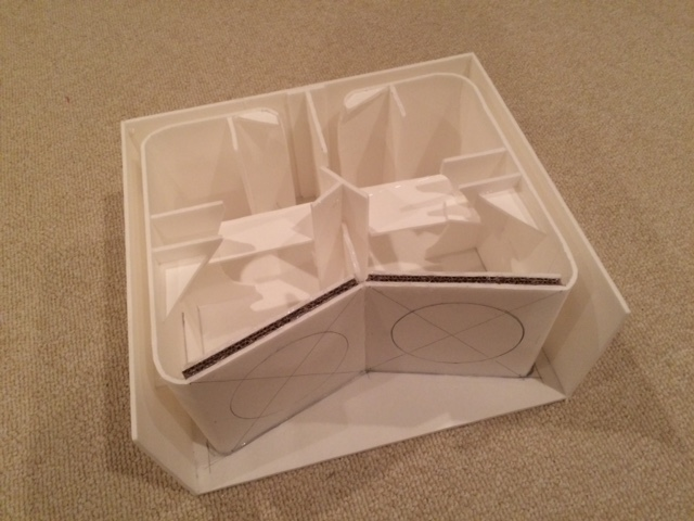
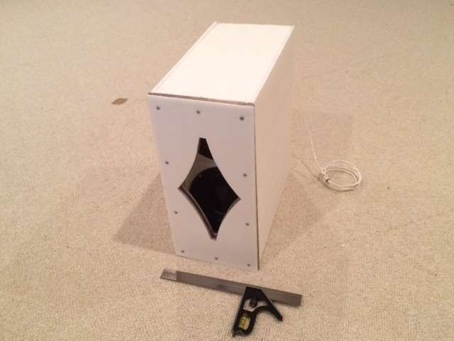
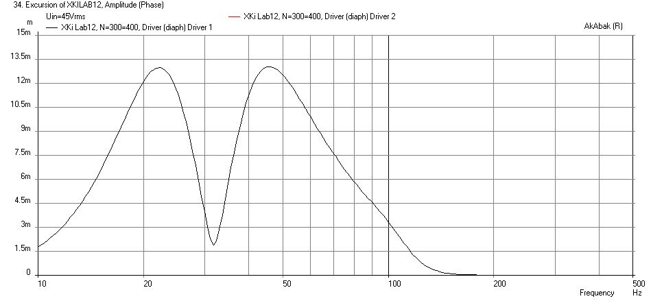
But modified to be much bigger and to use plywood instead of foam core. The basic design is to make the back chamber about 90 liters, the front chamber about 45 liters, connect the front and back chambers with two wrap around channel vents 12.5in tall x 1.25in wide x 23in long. The drivers are mounted in the V panel which divides the box into front and rear chambers. Wire the 8ohm drivers in parallel for a 4ohm load. The front aperture a diamond shape with curved edges as shown for a Karlson aperture. Xmax of 13mm is reached at 45 volts of drive, and corresponding max SPL is 123dB in 4pi space or 126dB in 2pi (half space) with f3 of 35Hz. Sims below use a 4th order Butterworth high pass filter at 24Hz and a 8th order Butterworth low pass filter at 110Hz.
Here is predicted max SPL:
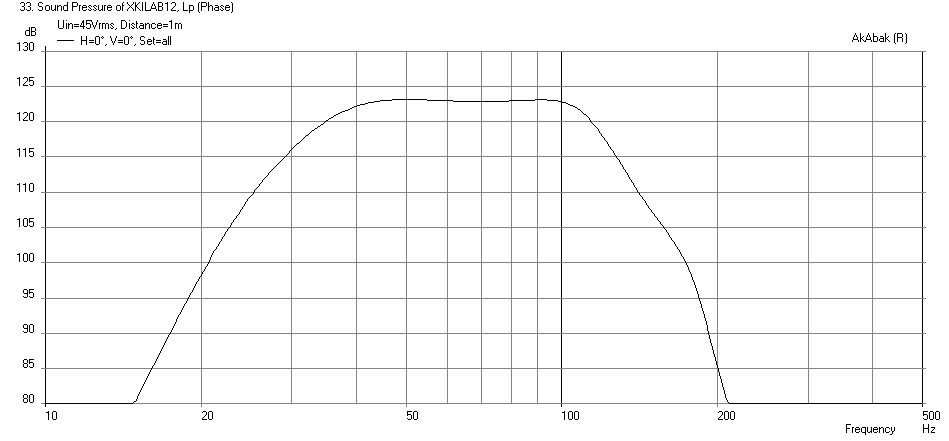
Here is predicted cone displacement at max SPL:
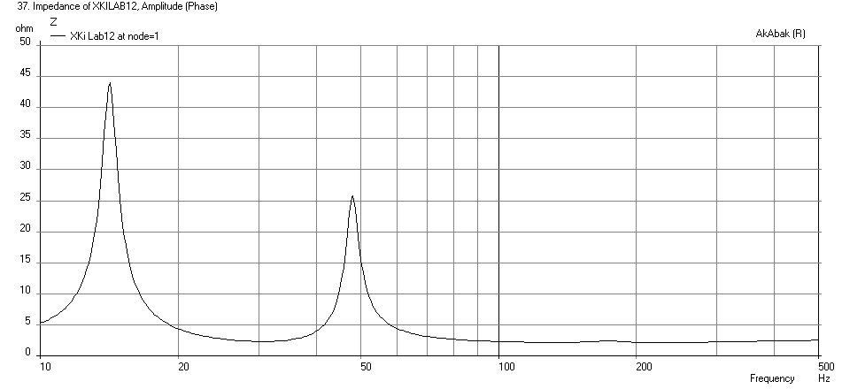
Here is electrical impedance:
Here is electrical power input at xmax:
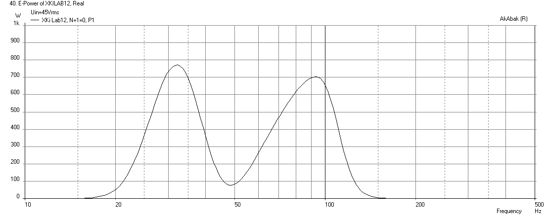
The one prototype that I built with 5.5in Tang Band sub drivers is very smooth with deep clean bass. The front chamber provides great cone control for the high power to extract SPL. You will need about 800 watts rms amp to hit the max SPL. Peak power should be substantially more.
The sketch of the design, which I believe just fits exactly into your space, is attached as pdf. I would use 3/4in plywood on exterior panels and driver mount baffle and 1/2in ply for internal channels dividers and braces.
Since you indicated that you have some Lab 12's you can use, I think this design may work. It is based on my XKi dual driver sub design shown here:
http://www.diyaudio.com/forums/full-range/268524-xki-xs-ab-initio-karlson-6th-order-bandpass-26.html#post4226956
But modified to be much bigger and to use plywood instead of foam core. The basic design is to make the back chamber about 90 liters, the front chamber about 45 liters, connect the front and back chambers with two wrap around channel vents 12.5in tall x 1.25in wide x 23in long. The drivers are mounted in the V panel which divides the box into front and rear chambers. Wire the 8ohm drivers in parallel for a 4ohm load. The front aperture a diamond shape with curved edges as shown for a Karlson aperture. Xmax of 13mm is reached at 45 volts of drive, and corresponding max SPL is 123dB in 4pi space or 126dB in 2pi (half space) with f3 of 35Hz. Sims below use a 4th order Butterworth high pass filter at 24Hz and a 8th order Butterworth low pass filter at 110Hz.
Here is predicted max SPL:
Here is predicted cone displacement at max SPL:
Here is electrical impedance:
Here is electrical power input at xmax:
The one prototype that I built with 5.5in Tang Band sub drivers is very smooth with deep clean bass. The front chamber provides great cone control for the high power to extract SPL. You will need about 800 watts rms amp to hit the max SPL. Peak power should be substantially more.
The sketch of the design, which I believe just fits exactly into your space, is attached as pdf. I would use 3/4in plywood on exterior panels and driver mount baffle and 1/2in ply for internal channels dividers and braces.
Attachments


Last edited:
- Status
- Not open for further replies.
- Home
- Loudspeakers
- Subwoofers
- high spl bass from L7 12's with SQ