First attempt at a custom circuit so please cut me a little slack.
Right now I'm only looking at how to determine what values R1 and R2 should be. Would anyone be so kind as to tell me how to do that?
We have a working, unloaded voltage. I'm thinking that I would need to come up with an estimated current draw, and then use ohm's law to determine resistance required. Not quite sure how to calculate current. Looking for a little direction. Thanks
notes: this circuit has the skeleton of a 5C3 power amp section with blank values for components and a different tube selection. This schematic is a work in progress with a partially working model to go along side it. So far there is heater supply and unloaded DC off of the cathode of the rectifier and that is all.
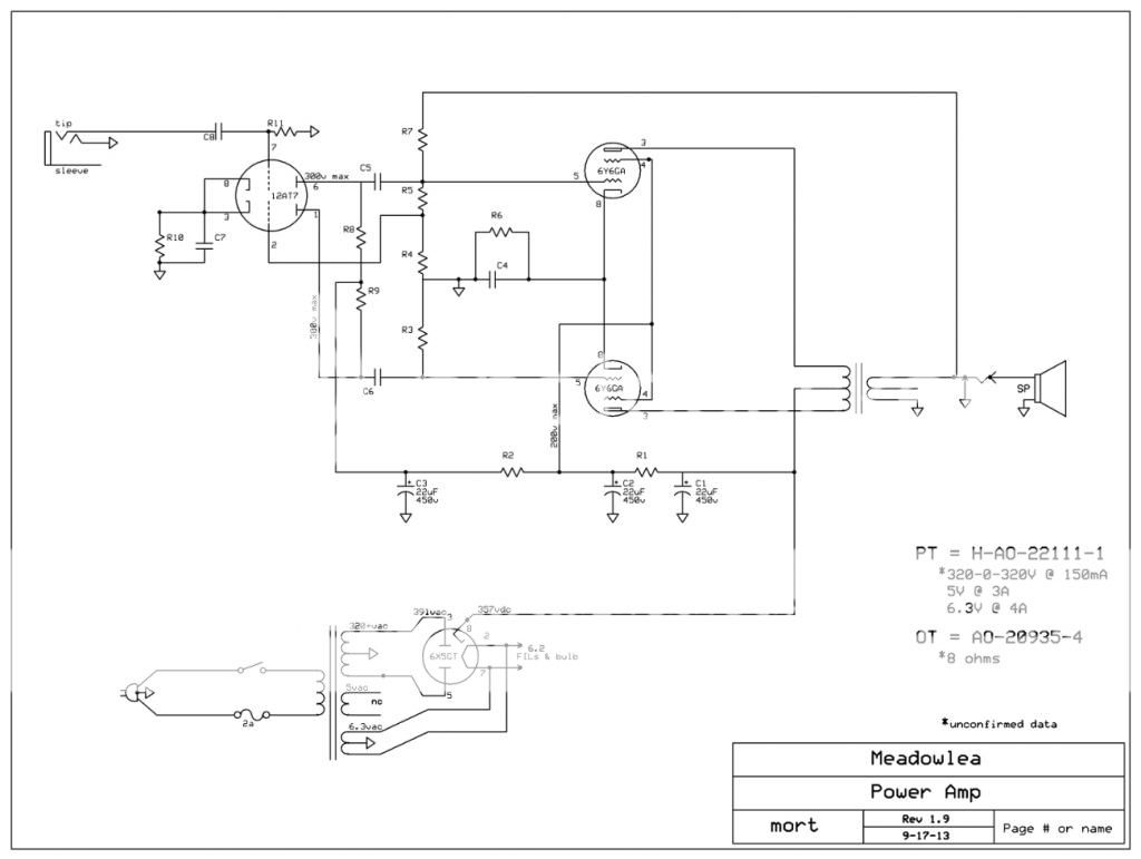
Last edited:
R = V / I
You know that.
Your question should be: How much current should I set my tubes to draw?
Then the rest is not too dificult.
Start with the data sheets for the tubes you are using.
Look at typical biasing examples for the tubes you are using. (or ones similar)
Learn how to use Load Lines with the Vp vs Ip vs Vg graphs, AKA Plate Characteristics. (And learn what those terms are)
Have fun.
- Status
- Not open for further replies.