Please forgive this extremely basic question, but I've been given a DAC evaluation board that I want to turn into a DAC I can use as line input to my speaker amplifier. I gather that I need to program it in order to to make sound. However, I've never used anything like this before and am not really sure how to go about it. I'd greatly appreciate any general advice, or if anyone happens to have set up DAC eval boards by AKM.
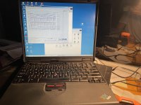
It's an Asahi Kasei 4413-SA (mfr. in 2012): coaxial and optical digital audio inputs, op-amp outputs, USB controller interface. It came with controller/measurement software that runs on Windows 2000. I had to dig out my 20-year old laptop in order to run the software and interface with the USB port on the board, which actually seems to work. But that's as far as I can get.
I've been trying to understand what it means to select or deselect the registers (things like "ACKS" that automatically detect input signal sample rates -- see attached pic). I'm guessing that I need to turn on the right ones by clicking their buttons and then "Writing" them to the processor via the software?
The manuals merely describe the features but provide no direction on how to set up a running DAC -- clearly it's meant for engineers or people who already know about these things.
I thought I'd turned on the ACKS and the four channel outputs. I've connected the CD player to the optical input, but no sound or even measurable voltage appears at the output BNC jacks.
Perhaps someone has set up an AKM eval board before? Any tips on getting started would be much appreciated.
Thanks!
Jeff
Attachments


Have you read the datasheet of the DAC chip, https://www.digikey.com/htmldatasheets/production/1212275/0/0/1/ak4413.html I have no experience with the AK4413, but usually a chip datasheet explains the meaning of the control bits more explicitly than an evaluation board manual.

Thank you. That datasheet is one of the files on the CD that came with the board. I've read it through several times, and reread the more pertinent sections several times, and keep going back to it as I try to understand the terms and their application in the software.
What I mainly need to know, though, is how to use the software to program the DAC. I.e., do I have to turn on certain features in order for them to work? There's a Sequence button -- do I need to string the registers together in a certain order as part of making the DAC operational, or is that just if I'm doing a computational measurement?
It's big-picture How-To stuff like that.
I wrote a series of posts in another thread about programming DAC chip registers with an Arduino, over I2C bus.
Registers are like memory locations in a computer or like the registers in a CPU. DAC registers are addressable for read and for writing to over a bus, in this case its usually I2C bus or SPI bus (some people refer to them as 3-wire, and 4-wire control, respectively).
Each register contains a set of eight bits, numbered from bit-0 to bit-7. Each register has its own address for you to access it. The register bits can be used to switch on or off some dac feature, control output volume, let you read information about the DAC chip status, almost for any purpose. What the registers do for a particular DAC chip is described in the datasheet.
The I2C bus standard is explained in the document at: https://i2c.info/i2c-bus-specification
It uses two signals called SCL and SDA, and a ground (3-wires altogether). The DAC datasheet should show which pins those are on the DAC chip you have.
The first of my posts about programming registers starts at: https://www.diyaudio.com/community/threads/es9038q2m-board.314935/post-6381151
The posts are spread out over several pages as the person learning in the thread, Daniel (aka Green777), keeps learning and asking questions.
Maybe an interesting part of the series for you would start at: https://www.diyaudio.com/community/threads/es9038q2m-board.314935/post-6386977
Last edited:
Ah, excellent. Thank you. I had searched the forum for tutorials like that but came up dry. I'm starting to read through it now. What you say in that thread about the portions of hexadecimal numbers makes sense wrt to things I see in the manuals and in the control software.
It seems the first step might be to read the DAC chip to see what features are turned on and off.
It seems the first step might be to read the DAC chip to see what features are turned on and off.
No need to read the DAC chip to find the default register settings. They are described in the datasheet.
However, if you have an MCU that came with a DAC board, then it could be programming the registers to some non-default settings. The start of the series I wrote describes one way to deal with that situation. It also describes hardware interfacing of I2C bus. After that is where I started talking about programming.
However, if you have an MCU that came with a DAC board, then it could be programming the registers to some non-default settings. The start of the series I wrote describes one way to deal with that situation. It also describes hardware interfacing of I2C bus. After that is where I started talking about programming.
OK, thank you. It appears the control program interface arranges the bits according to their addresses by rows. I gather that one executes the programming by selecting various features to be in the 1 (pressed down) or 0 (left up) positions, and then clicking on the Write button at the end of the row in order to set the features at that address on the chip. The attached screenshot from the manual shows the software interface exactly as it appears to me, plus some basic explanation.

I think you are right. It's similar to evaluation board user interfaces of chips that I am familiar with, and it makes sense because control bits are written one register at a time.
DAC evaluation boards are primarily meant for designers planning to use the DAC chip in their own designs so they offer the flexibility to try out the various features and external circuitry (e.g. power supplies). Evaluation boards are not ideal for end-users.The manuals merely describe the features but provide no direction on how to set up a running DAC -- clearly it's meant for engineers or people who already know about these things.
Based on you register settings you have not turned ACKS on. But that is probably not the cause for your problem. Check all power supplies as well as jumpers & switches as rfbrw suggested.I thought I'd turned on the ACKS and the four channel outputs. I've connected the CD player to the optical input, but no sound or even measurable voltage appears at the output BNC jacks.
Tips that may do the trick or may make a brick:I thought I'd turned on the ACKS and the four channel outputs. I've connected the CD player to the optical input, but no sound or even measurable voltage appears at the output BNC jacks.
Perhaps someone has set up an AKM eval board before? Any tips on getting started would be much appreciated.
1. Make sure you have CD data exiting out the toslink - plug it into a working DAC to check or at least make sure the toslink glows red on playing the CD
2. Select ACKS on and stereo out (selecting four channels out with stereo SPDIF in is not a match)
3. When you have music write and save. Exit, power off , power on check the software to make sure its all good
4. Play with the software settings eg try the slow roll off filters. Make just one change at a time so you know how to undo a bad change.
5. Have fun.
Thanks, MarcelvdG, rfbrw, bohrok2610, and kazap. Here are responses to your queries and suggestions. Nearly all my DIY builds have been point-to-point wired tube amps and wooden loudspeakers, so please forgive the extremely basic understanding of PCBs.What position are the jumpers and switches set to ?
The CD Player optical output works: the cable end glows red when it is running a CD and it works with another DAC that I have.
Power is from an external DC supply of +15V, -15V, and ground, as specified in the DAC board documentation.
There are two manually accessible jumpers on the board, JP1 and JP2 (document and board pictured): according to the documentation, open jumpers (cap off?) put the board in serial control mode, while closed jumpers (cap on?) put it in parallel control mode (the default). They currently have caps on, which I assume makes them closed and put the board in the default parallel control mode. The datasheet and manual provide different settings on the DAC chip pins for serial and parallel control modes. I believe it ought to be be in parallel control mode, which it is at present.
There are two sets of 6 DIP switches for the control register (see attached block diagram) that are in the default positions as defined by the manual (see attached images from the manual and of the switches themselves); I never changed these. The switch for ACKS is "on" (manual mode). In the documentation, under parallel control mode (pictured), it appears the ACKS should be set to "on" (called "Manual") in the control register ("Manual" mode detects all the possible standard sampling frequencies); so yes, it appears I should click the ACKS button "on" in the software and write it to the register, in order for it to be able to read data from the CD player optical out.
But I'm actually not sure if I'm using the board correctly for adjusting the settings with the software. That's because:
There are two "PDN" switches on the board labeled SW1 and SW2 (pictured). According to documentation Section 4 (pictured), I need to power up the board and then turn these switches to the "L" position "once" in order to power-down reset the AK4413 and AK4118A, and then return them to the "H" position for "normal" operation. What's not clear to me is whether ...
(1) these switches need to be in the "L" position while I'm using the software to change the register settings, after which I return them to "H,"
or
(2) I turn them to "L" and then back to "H" as a hard reset BEFORE I use the software to change the register settings (while they're at "H")
Finally: Outputs -- The board has 4 BNC sockets on the output side: LOUT1, ROUT1, LOUT2, ROUT2 (reflected in the attached function diagram, right side). I only need 2-channel stereo, so I'm not sure if I should only enable one pair of L & R outputs or if I should put them in parallel.
Also, I assumed these outputs were single-ended but maybe they're differential ("balanced")?
And also, I assumed these BNC sockets are for analog audio output (not digital data), which I tried to connect to a tube amp input.
Attachments
-
 jumpers.jpg406.5 KB · Views: 72
 -
 power-switches.png361.4 KB · Views: 83
 -
 switch-table.png183.1 KB · Views: 86
 -
 switch-table-02.png890.7 KB · Views: 74
 -
 switches.jpg532.3 KB · Views: 64
 -
 ps-jumpers-switches.png1,009.8 KB · Views: 83
 -
 diagram-block.png2.4 MB · Views: 79
 -
 acks-pcm.png1 MB · Views: 73
 -
 diagram-function.png2.1 MB · Views: 89
Last edited:
Since you have set the board to parallel mode the register settings via SW are not used. So only jumpers and switches.
For reseting the board you should set both PDN switches to "H" before powering the board. After power up switch both to "L" shortly and return them to "H".
For reseting the board you should set both PDN switches to "H" before powering the board. After power up switch both to "L" shortly and return them to "H".
I didn't know that only serial mode allows you change settings through the software, so thank you. The manual says nothing about that.Since you have set the board to parallel mode the register settings via SW are not used. So only jumpers and switches.
For reseting the board you should set both PDN switches to "H" before powering the board. After power up switch both to "L" shortly and return them to "H".
Given that it's in parallel mode, it appears all the switches are set correctly. The problem is then to figure out why there's no music on the outputs. I was connecting clipped leads from the conductors of the left channel #1 and right channel #1 BNC output sockets to the appropriate ring on a 1/8" stereo headphone jack (i.e. left channel to tip, right channel to middle collar, ground ring to circuit board ground) that's on one end of an interconnect that terminates in RCA plugs on the other end.
I would think that ought to work. But maybe I should switch to serial mode so that I can tweak it through the software.
It should be easier to get the board working in parallel mode. Then you can switch to serial mode.
Could you show a picture of the output connectors. There are cheap BNC-RCA adapters available in many places. Such as this: https://www.partco.fi/en/connector-adapters/bnc_adapters/8871-ad-bnc-u-rca-n.html
Could you show a picture of the output connectors. There are cheap BNC-RCA adapters available in many places. Such as this: https://www.partco.fi/en/connector-adapters/bnc_adapters/8871-ad-bnc-u-rca-n.html
Sure. Here's a pic of the board with the four BNC sockets. Two currently have BNC cables in them, which have RCA adapter plugs on the other end. Clipped leads attach to the RCA pin and go to the appropriate ring on a stereo headphone jack, which is on one end of an interconnect cable that has RCA plugs on the other end. Those go into the amplifier RCA input sockets.
The amp is a breadboard with a circuit I've been developing: type 27 input tube cap-coupled to 6N6G output tube (internally connected Loftin-White driver and output triode in the same bottle: you just connect the cathode to ground and supply the correct plate voltage). It has a terrible damping factor but sounds wonderful with very efficient Lowther single full range drivers. I usually play it direct from CD player or iPhone (onboard DACs), and thought it would be fun to use this fancy eval board DAC instead.
The amp is a breadboard with a circuit I've been developing: type 27 input tube cap-coupled to 6N6G output tube (internally connected Loftin-White driver and output triode in the same bottle: you just connect the cathode to ground and supply the correct plate voltage). It has a terrible damping factor but sounds wonderful with very efficient Lowther single full range drivers. I usually play it direct from CD player or iPhone (onboard DACs), and thought it would be fun to use this fancy eval board DAC instead.
Attachments


Last edited:
Have you reversed R46 and R48 ? Rather than use the switchable inputs of the AK4118A, AKM chose, for simplicity I assume, to use a single input on the AK4118A and physically switch inputs as needed. For the optical to work you will have open R48 isolating the coax input and link across R46 connecting the optical input.
I've not done that, in part because I've not been able to visually locate R46 and R48 on the circuit board, and in part because the diagram (see lower left, attached) appears to show both the coaxial and optical inputs leading to the same pin on the chip (#48). I didn't think it required me to change anything, but I'll keep looking. Maybe it's one of the switches, but it doesn't seem to be drawn that way.
EDIT: Never mind, they're on the underside and, man, they are tiny (attached).
EDIT: Never mind, they're on the underside and, man, they are tiny (attached).
Attachments


- Home
- Source & Line
- Digital Line Level
- How to Use a DAC Evaluation Board?